ccei PF10R511 Owner's manual
Technical instructions
P/N: PF10R511 / PF10R508 / PF10R521
Table of Contents
1. Important safety instructions ........................................................................................................ 2
2. System overview ......................................................................................................................... 3
2.1. Package contents .............................................................................................................. 3
2.2. System component specifications and dimensions ............................................................ 3
3. 4-light controller installation (PF10R511) .................................................................................... 4
3.1. Controller box mounting ................................................................................................... 4
3.2. Power supply wiring ......................................................................................................... 5
4. 8-light controller installation (PF10R508) .................................................................................... 6
4.1. Controller box mounting ................................................................................................... 6
4.2. Power supply wiring ......................................................................................................... 7
5. 16-light controller installation (PF10R521) .................................................................................. 8
5.1. Controller box mounting ................................................................................................... 8
5.2. Power supply wiring ....................................................................................................... 10
6. Send a DMX data to a controller and extend the signal to 2 or more controllers ......................... 12
6.1. Configure a controller using its DIP SWITCH (applicable if you have more than 1 con-
troller) .................................................................................................................................... 16
7. Enjoy your new lighting ............................................................................................................ 17
8. Troubleshooting ......................................................................................................................... 18
8.1. Power supply troubleshooting ......................................................................................... 18
8.2. Controller troubleshooting .............................................................................................. 19
8.3. Light troubleshooting ...................................................................................................... 19
9. Warranty .................................................................................................................................... 20
A. Technical support ................................................................................................................... 20
Read these instructions carefully before installing, commissioning and using this
product.
Lights must never be turned on outside of water.
For supply connection, use only an isolating low voltage power supply with
ungrounded output, evaluated for swimming pool use.
CONT0037 v2.0CAEN (04/08/2020)
Technical instructions v2.0CAEN
1. Important safety instructions
This product must be installed by a licensed or certified electrician or a qualified
pool professional in accordance with the current National Electrical Code (NEC),
NFPA 70 or the Canadian Electrical Code (CEC), CSA C22.1. All applicable local
installation codes and ordinances must also be adhered to. Improper installation
will create an electrical hazard which could result in death or serious injury to pool
users, installers or others due to electrical shock, and may also cause damage to
power source. Always disconnect the power to the pool light at the circuit breaker
before servicing the light. Failure to do so could result in death or serious injury
to service person, pool users or others due to electrical shock.
For countries in compliance with International Electrotechnical Commission
(IEC) regulatory standards: The light fixture must be installed by a licensed or
certified electrician or a qualified pool service person, in accordance with current
IEC 364-7-702 and all applicable local codes and ordinance. Improper installation
will create an electrical hazard, which could result in death or serious injury to
pool user, installer or other due to electrical shock and may also cause damage to
the property.
ccei.ca 2
Technical instructions v2.0CAEN
2. System overview
2.1. Package contents
• DMX Drivers Box x4, x8 or x16 lights
• Wall mounting accessories
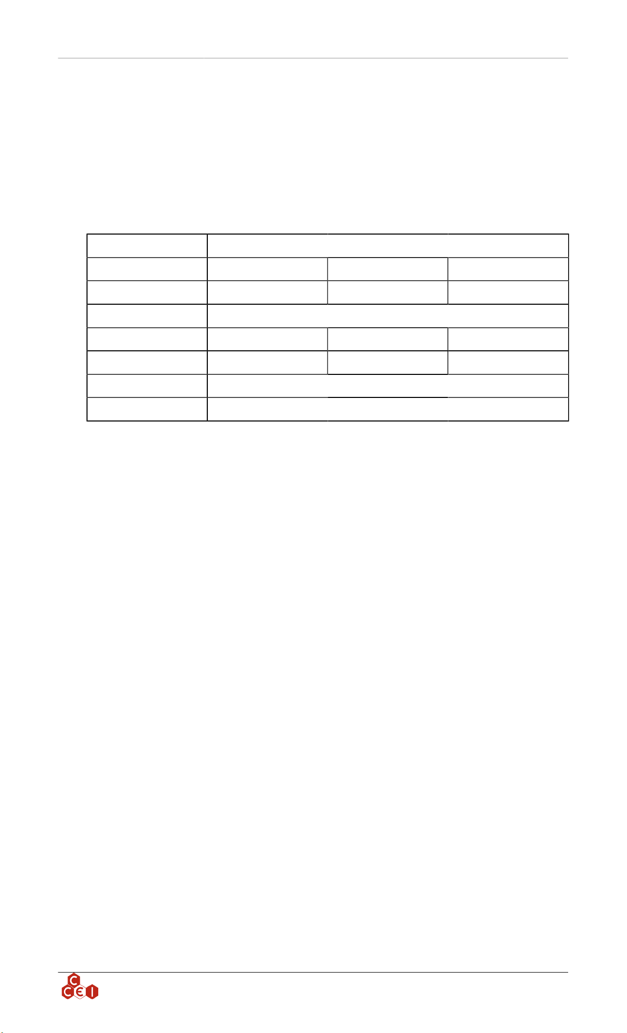
2.2. System component specifications and dimensions
DMX Drivers Boxes *
Part Number x4 PF10R511 x8 PF10R508 x16 PF10R521
Max # Lights 4 8 16
Power Supply Power Supply: 24V-DC50/60Hz IP:65
Max Power 90 W 180 W 360 W
Dimensions Inches 9 x 11.5 x 6 TBD 14.4 x 10.4 x 5.3
DMX Input 3-wire terminal block
DMX Output 3-wire terminal block
* Driver boxes can be linked together with 3 wires, a maximum of 512 DMX channels can be controlled.
ccei.ca 3
Technical instructions v2.0CAEN
3. 4-light controller installation (PF10R511)
3.1. Controller box mounting
3.1.1. 4-light controller
1. Unscrew the front panel of the Driver Box to access the DMX Drivers.
2. Bring the Lights cable to the sides of the Driver Box using conduits.
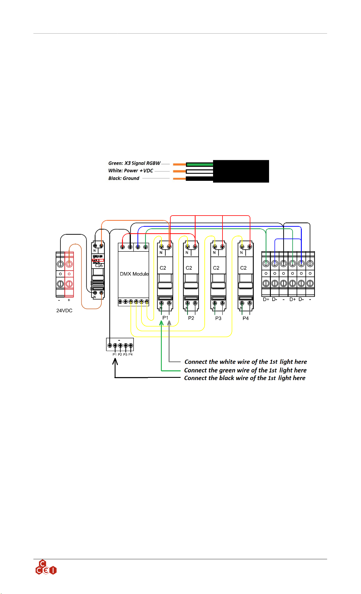
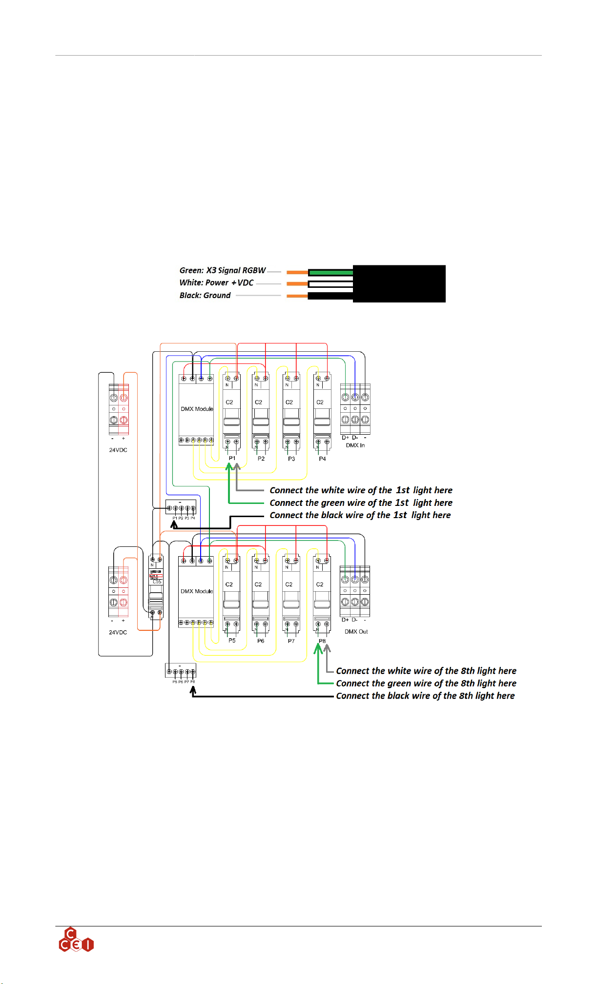
3.1.1.1. Lights wiring
The lights cable comes with 3 wires:
Each light must be connected to the controller as shown in the scheme below (one light per C2 light
breaker):
If you have more than one light, repeat the operation using P2, P3 and P4 (up to 4 lights with this
controller)
ccei.ca 4
Technical instructions v2.0CAEN
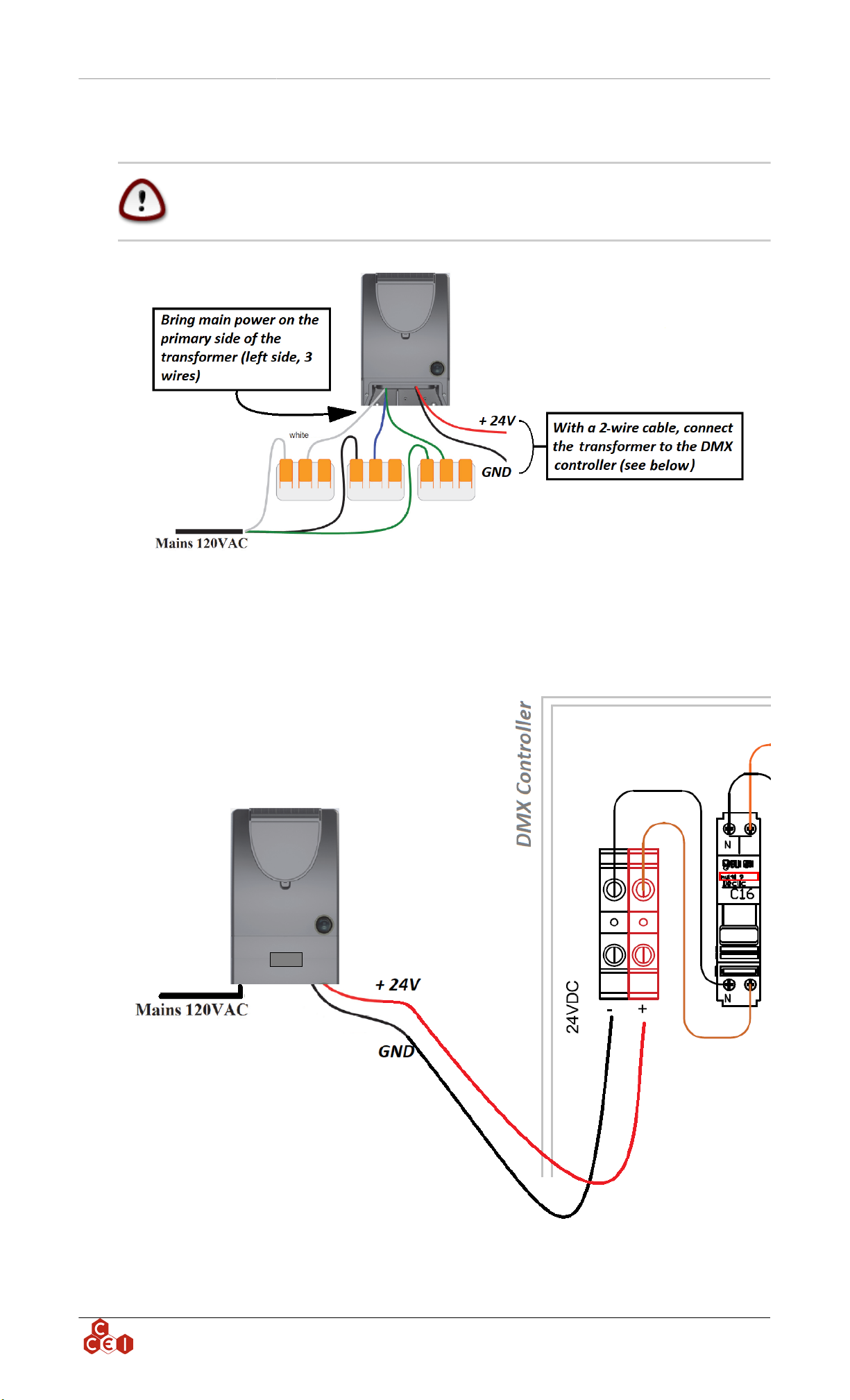
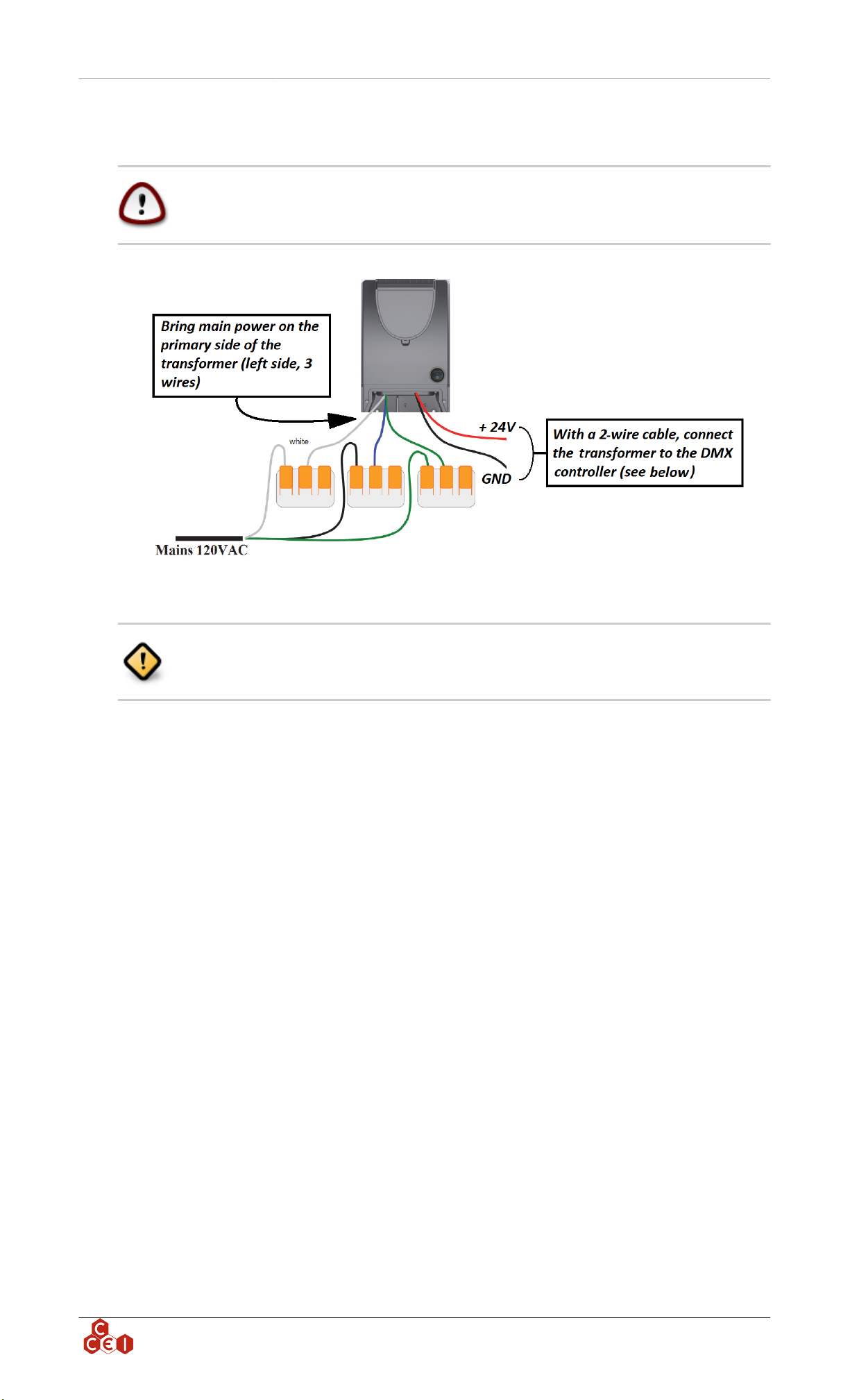
3.2. Power supply wiring
CCEI USA Inc DMX Solutions are powered by its 24V DC power supply; Please
follow the steps below carefully, we recommend this operation be carried out by
an approved electrician.
Using the 2-wire cable connected at the secondary of the DC power supply bring power through a
conduit to the Driver Box by connecting the wires to the black and red terminal blocks. (Respect the
color)
ccei.ca 5
Technical instructions v2.0CAEN
4. 8-light controller installation (PF10R508)
4.1. Controller box mounting
4.1.1. 8-light controller
1. Unscrew the front panel of the Driver Box to access the DMX Drivers.
2. Bring the Lights cable to the sides of the Driver Box using conduits.
4.1.1.1. Lights wiring
The lights cable comes with 3 wires:
Each light must be connected to the controller as the scheme below (one light per light breaker C2):
If you have many lights, repeat the operation using P2, P3, P4, P5, P6, P7, P8 (up to 8 lights with this
controller)
ccei.ca 6
Technical instructions v2.0CAEN
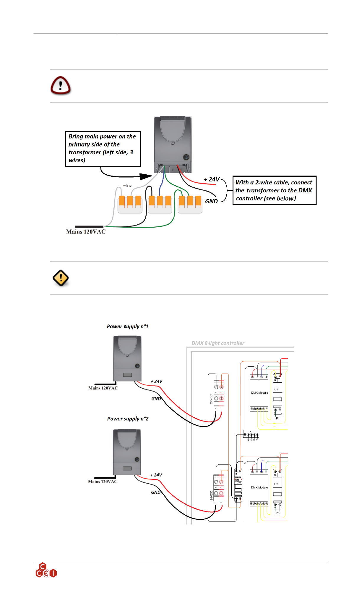
4.2. Power supply wiring
CCEI USA Inc DMX Solutions are powered by its 24V DC power supply; Please
follow the steps below carefully; we recommend this operation be carried out by
an approved electrician.
The 8-light controller needs 2 power supplies repeat the previous step.
Using the 2-wire cable connected at the secondary of the DC power supply bring power trough a conduit
to the Driver Box by connecting the wires to the black and red terminal blocks. (Respect the color)
ccei.ca 7

Technical instructions v2.0CAEN
5. 16-light controller installation (PF10R521)
5.1. Controller box mounting
5.1.1. 16-light controller
1. Unscrew the front panel of the Driver Box to access the DMX Drivers.
2. Bring the Lights cable to the sides of the Driver Box using conduits.
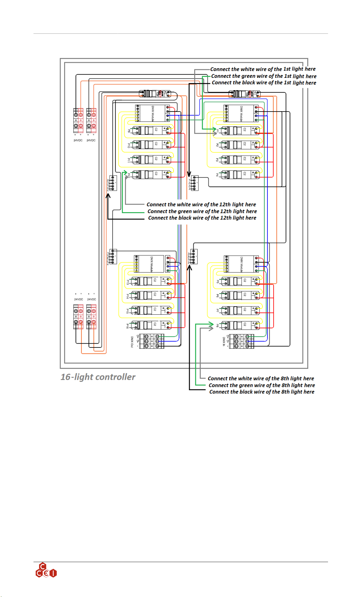
5.1.1.1. Lights wiring
The lights cable comes with 3 wires:
Each light must be connected to the controller as shown in the scheme below (one light per C2 light
breaker):
ccei.ca 8
Technical instructions v2.0CAEN
If you have many lights, repeat the operation using P1 to P16 (up to 16 lights with this controller)
ccei.ca 9
Technical instructions v2.0CAEN
5.2. Power supply wiring
CCEI USA Inc DMX Solutions are powered by its 24V DC power supply; Please
follow the steps below carefully; we recommend this operation be carried out by
an approved electrician.
Each group of 4 lights needs a 24 VDC power supply, repeat the operation 2 times
for 12 lights, 3 times for 16 lights
Using the 2-wire cable connected at the secondary of the DC power supply bring power through a
conduit to the Driver Box by connecting the wires to the black and red terminal blocks. (Respect the
color)
ccei.ca 10
This manual suits for next models
2
Table of contents
Other ccei Lighting Equipment manuals

ccei
ccei Brio PK10R400 Owner's manual

ccei
ccei Limpido EZ DUO 60 User manual

ccei
ccei Brio WX-100 User manual

ccei
ccei Mini Brio 2 X3 color Owner's manual

ccei
ccei Mini BRIO M12CA User manual

ccei
ccei BRIO A300C Manual

ccei
ccei NIVA 3 Owner's manual

ccei
ccei LIMPIDO LTE DUO User manual

ccei
ccei Mini Brio X15CA Owner's manual

ccei
ccei Zelia ZLT User manual
Popular Lighting Equipment manuals by other brands


Qazqa
Qazqa Suplux SL 3 Black 103062 instruction manual

Commercial Electric
Commercial Electric 54568141 Use and care guide

CREE LIGHTING
CREE LIGHTING 304 Series installation instructions

Goobay
Goobay 49867 user manual

ECOMAN ITALIA
ECOMAN ITALIA LED T8 instruction manual

Alkalite
Alkalite Krypton KT-81 user manual


