Catch Power SOLAR RELAY Operation manual


IMPORTANT
This product must be installed by a
licensed electrician. This product must be
installed according to the AS/NZ3000 –
Australian Wiring Standards.
DANGER
Danger to life due to high voltage AC
Always ensure all electricity sources are
appropriately isolated when installing this
piece of equipment.
CATCH Power SOLAR RELAY –Installation Manual - Page 2
DANGER
Electric Shock Risk with CT’s
CT’s must be fitted to insulated cables
only. Ensure CT is terminated into the
device before clamping onto cables.

Specifications
CATCH Power SOLAR RELAY –Installation Manual - Page 3
Operational Voltage 230VAC
Operational Frequency 50Hz
Maximum AC Load 4A
Load Types Any
Max A/C Cable Size 2.5mm2
CT lead length 1m
IP Rating IP2X
Operating Temperature range -20oC to +45oC
Size 35W x 85H x 65D (mm)
Standards Conformity IEC 60730-1, AS/NZS CISPR 32:2015
Inside the package
1 x CATCH Solar Relay
1 x Current Transformers

CATCH SOLAR RELAY Installation
CATCH Power SOLAR RELAY –Installation Manual - Page 4
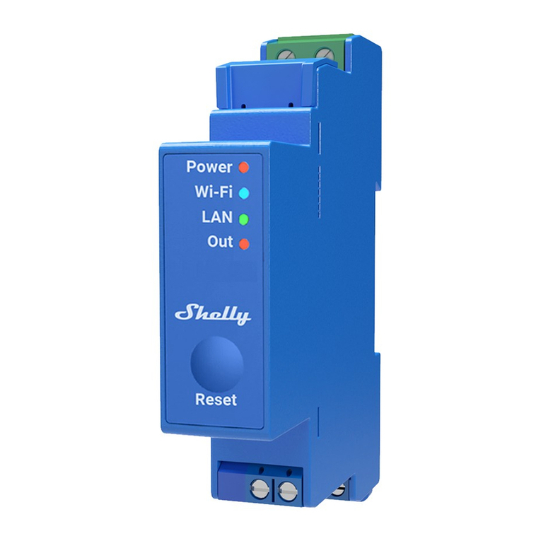
CATCH Solar Relay has been designed specifically for the solar industry, as such the
terminal layouts are designed for maximum flexibility and simplicity of wiring.
Highlights on the installation are:
•DIN Mounted.
•Same size as a 2
Pole miniature
circuit breaker
Duplicated power
terminals for easy
daisy chaining.
•CATCH Solar Relay is the size of a 2 pole miniature circuit
break, it must be mounted inside an electrical enclosure
such as a switch board, sub board, load centre, or any
other enclosure designed to house electrical switch gear.
CATCH Solar relay is designed to be DIN mounted inside a
standard miniature circuit breaker cover.
•CATCH Solar Relay is designed to control loads via an
external contactor. This means the number and type of
loads controllable by CATCH Solar Relay is only limited by
your imagination.
CATCH Solar Relay can control one or more contactor coils
(up to a maximum load current of 4A). CATCH Solar Relay
will happily drive one or more single or 3 phase contactors.
•Power terminals are duplicated for easy daisy chaining to
other power control devices.

INSTALLATION - Overview
CATCH Power SOLAR RELAY –Installation Manual - Page 5
Before Going to Site:
•Download the CATCH Power Configuration App to your phone. The App can be
downloaded from Google Play Store or the Apple iStore.
Onsite Site:
•Install CATCH Solar Relay as per the circuit diagram below.
•Power the device up and connect to it using the CATCH Power Configuration App
on your phone or tablet. The Configuration App uses Bluetooth to communicate
with the CATCH Solar Relay.
•Adjust the device settings to suit the installation.

CATCH Power SOLAR RELAY –Installation Manual - Page 6
INSTALLATION –Circuit Diagram
Cable Sizes:
Maximum wire size for the Solar Relay is 2.5mm2.
Contactor:
Contactor selection should be made based on load requirements. The solar relay
requires the coil voltage to be 240VAC, with a maximum coil current of 4A.
Current Transformer:
If the export control feature of CATCH Solar Relay is required then the CT must be
installed. The CT can be positioned anywhere in the installation that sees all loads
and solar.
Type AC
10A RCDBO

CATCH Power SOLAR RELAY –Installation Manual - Page 7
INSTALLATION - Cable Termination
Ideal cable size 1.5mm2 Maximum cable size is
2.5mm2
There are 3 connections that need to be made on
the bottom of the CATCH Relay, each connection
can be made from one of two connection points.
For example: The Active IN connection point is
made from one of the left two connectors. You
can choose either one, as they are bussed
together inside the device.
Example:
Wiring for a basic installation. As you can see it
does not matter which of the two terminals you
choose for each connection.
Active In
Active Out
Neutral

CATCH Power SOLAR RELAY –Installation Manual - Page 8
•The arrows next to the CT’s in the wiring diagram represent the
arrows on the inside of the CT’s.
•Matching the CT’s to the correct phase is critically important
special care must be taken to ensure this happens.
•NEVER disconnect CT’s from the Solar Relay while they are
wrapped around a current carrying conductor.
•Multiple wires can be put through the CT, as long as all currents are
in the same direction and in phase.
IMPORTANT Current Transformer Rules
IMPORTANT
INSTALLATION –Current Transformer

CATCH Power SOLAR RELAY –Installation Manual - Page 9
IMPORTANT
It is vitally important the CT’s are
pointing in the right direction.
Mains
DANGER
Electric Shock Risk with CT’s
CT’s must be fitted to insulated cables
only. Ensure CT is terminated into the
device before clamping onto cables.

CATCH Power SOLAR RELAY –Installation Manual - Page 10
INSTALLATION –Current Transformer
Match the CT wire colours to the labels on the case.
Note there is a 1 terminal gap between the white and black wire.
Solar Relay Terminal CT wire colour
W white
BLK Black
Table of contents