cascade corporation F Series User manual

Cascade is a Registered Trademark of Cascade Corporation
cascade
corporation
ERVICE MANUAL
S
F-Series
Double-Wide Sideshifter
Manual Number 6903351

i6903351
CONTENTS
Page
INTRODUCTION, Section 1
Introduction 1
Special Definitions 1
PERIODIC MAINTENANCE, Section 2
Daily 2
1000-Hour Maintenance 2
2000-Hour Maintenance 2
TROUBLESHOOTING, Section 3
General Procedures 3
Truck System Requirements 3
Tools Required 3
Troubleshooting Chart 3
Plumbing 4
Hosing Diagram –Independent Sideshift 4
Hydraulic Schematic –
Independent Sideshift 5
Hosing Diagram –
Simultaneous OPEN/CLOSE 6
Hydraulic Schematic –
Simultaneous OPEN/CLOSE 6
Hosing Diagram –Simultaneous
OPEN/CLOSE and LEFT/RIGHT 7
Hydraulic Schematic –Simultaneous
OPEN/CLOSE and LEFT/RIGHT 8
Sideshift Frames 9
Supply Circuit Test 9
Independent Sideshift Circuit Test 10
Simultaneous LEFT/RIGHT Sideshift
Frame Circuit Test 11
Simultaneous OPEN/CLOSE Sideshift
Frame Circuit Test 12
Electrical Circuit 13
Page
SERVICE, Section 4
Attachment Removal 14
Sideshift Frames Removal 14
Base Frame Removal 15
Frame Service 16
Bearing Lubrication 16
Sideshift Frame Bearing Service 17
Base Frame Bearing Service 18
Cylinder Service 19
Removal and Installation 19
Rod Seal Replacement 20
Valve 21
Valve Removal 21
Valve Service 21
Solenoid Valve 22
Coil Service 22
Valve Service 22
SPECIFICATIONS, Section 5
Specifications 23
Hydraulics 23
Auxiliary Valve Functions 23
Truck Carriage 24
Torque Values 25

INTRODUCTION
16903351
1.2 Special Definitions
The statements shown appear throughout this manual
where special emphasis is required. Read all WARNINGS
and CAUTIONS before proceeding with any work.
Statements labeled IMPORTANT and NOTE are provided
as additional information of special significance or to make
the job easier.
WARNING - A statement preceded by
WARNING is information that should be
acted upon to prevent bodily injury. A
WARNING is always inside a ruled box.
CAUTION - A statement preceded by CAUTION is
information that should be acted upon to prevent
machine damage.
IMPORTANT - A statement preceded by IMPORTANT is
information that possesses special significance.
NOTE - A statement preceded by NOTE is information that
is handy to know and may make your job easier.
1.1 Introduction
This manual provides the Periodic Maintenance, Troubleshooting,
Service and Specifications for Cascade F-Series Double-Wide
Sideshifters.
In any communication about the attachment, refer to the product
catalog and serial numbers stamped on the nameplate. If the
nameplate is missing, the numbers can be found stamped on the
base frame where the plate was mounted.
IMPORTANT: All hoses and fittings on F-Series Double-Wide
Sideshifters are JIC as standard, with metric and face seal as an
option.
NOTE: Specifications are shown in US and (metric) units where
applicable. All fasteners have a torque value range of ±10% of
stated value.
Nameplate
SS1437.eps

26903351
PERIODIC MAINTENANCE
SS1422.eps
WARNING: After completing any service
procedure, always test the attachment
through five complete cycles. First test
empty, then test with load to make sure
attachment operates correctly before
returning it to the job.
2.1 Daily
Check the items shown each day. Report problems to the
on-duty supervisor. Refer to Section 3 for Troubleshooting
and Section 4 for Service procedures.
2.2 1000-Hour Maintenance
Every time the lift truck is serviced or every 1000 hours
of truck operation, complete the following maintenance
procedures:
• Check for loose or missing bolts, worn or damaged
hoses, hydraulic leaks, and damaged or missing
fork stops.
• Inspect lower hooks for wear and proper clearance.
Adjust if necessary, refer to the Section 4.1-2,
Step 4. Tighten lower hook capscrews to 120 ft.-lbs.
(165 Nm).
• Tighten backrest capscrews (Cascade) to
145 ft.-lbs. (195 Nm).
• Inspect upper and lower bearings for wear. If any
bearing is worn to less than 0.09 in. (2.5 mm)
thickness, replace the entire bearing set. Refer to
Sections 4.2-2 and 4.2-3.
• Apply general-purpose chassis grea se to sideshift
frame upper and lower bearings.
2.3 2000-Hour Maintenance
After 2000 hours of truck operation, in addition to the
daily inspections and 1000-hour maintenance, forks
in use shall be inspected at intervals of not more than
12 months (for single shift operations) or whenever any
defect or permanent deformation is detected. Severe
applications will require more frequent inspection.
Fork inspection shall be carried out by trained
personnel to detect any damage that might impair safe
use. Any fork that is defective shall be removed from
service. Reference ANSI B56.1-2005.
Inspect for the following defects:
• Surface cracks
• Straightness of blade and shank
• Fork angle
• Difference in height of fork tips
• Positioning lock
• Wear on fork blade and shank
• Wear on fork hooks
• Legibility of marking
NOTE: Fork Safety Kit 3014162 contains wear calipers,
inspection sheets and safety poster. Also available is
fork hook & carriage wear gauge 209560 (Class II).
WARNING: If the fork locking pin is not
fully engaged, the fork could become
disengaged from the carriage.
Forks
Cylinders and
hoses for leaks
Backrest
Fork Lock Pins Fork Stops
Upper and lower
hook engagement
Fasteners

TROUBLESHOOTING
36903351
3.1 General Procedures
3.1-1 Truck System Requirements
• Truck hydraulic pressure should be within the range
shown in Specifications, Section 5.1. PRESSURE TO
THE ATTACHMENT MUST NOT EXCEED 3500 psi
(240 bar).
• Truck hydraulic flow should be within the range shown in
Specifications, Section 5.1.
• Hydraulic fluid supplied to the attachment must meet
the requirements shown in Specifications, Section 5.1.
3.1-2 Tools Required
In addition to a normal selection of mechanic's hand tools,
the following are required:
• In-line Flow Meter Kit:
10 GPM (37 L/min) – Cascade Part No. 671476
• Pressure Gauge Kit:
5000 psi (345 bar) – Cascade Part No. 671212
• Assorted fittings, hoses, and quick-disconnect couplers
as required.
WARNING: Before servicing any
hydraulic component, relieve pressure
in the system. Turn the truck off and
move the truck auxiliary control valves
several times in both directions.
After completing any service procedure, test the
attachment through several cycles. First test
the attachment empty to bleed any air trapped
in the system to the truck tank. Then test the
attachment with a load to be sure it operates
correctly before returning to the job.
Stay clear of the load while testing. Do not raise
the load more than 4 in. (10 cm) off the floor while
testing.
GA0013.eps
GA0014.eps
AC0127.eps
Flow Meter Kit:
671476 – 10 GPM (37 L/min)
(2) No. 8
JIC/O-Ring Flow Meter
(2) No. 6-8
JIC Reducer
Pressure Gauge Kit:
671212
Pressure
Gauge ▲No. 6-6 Hose ▲
No. 6 and No. 8
JIC Swivel Tee
No. 6-8 JIC
Reducer
No. 4, No. 6 ▲
and No. 8
JIC/O-Ring
No. 4-6
Pipe/JIC ▲
▲NOTE: Diagnostics Kit 394382
includes items marked.
Male Straight Thread
O-Ring Coupler:
No. 4 (Part No. 212282) ▲
No. 5 (Part No. 210378)
No. 6 (Part No. 678592)
Female JIC Thread
Coupler:
No. 4 (Part No. 210385) ▲
No. 6 (Part No. 678591)
Quick-Disconnect Couplers
3.1-3 Troubleshooting Chart
Determine All The Facts – It is important that all
the facts regarding the problem are gathered
before beginning service procedures. The first
step is to talk to the equipment operator. Ask for
a complete description of the malfunction. The
following guidelines can be used as a starting point
to begin troubleshooting procedures:
• Attachment sideshift frame does not sideshift or
open/close.
• Attachment sideshift frame(s) move slowly.
To correct these problems, see Section 3.3.

46903351
TROUBLESHOOTING
SS1448.eps
3.2 Plumbing
3.2-1 Hosing Diagram – Independent Sideshift
Two Auxiliary Control Valves
Solenoid
LEFT SIDESHIFT FRAME,
SIDESHIFT RIGHT
PRESSURE
RETURN
NOTE: For SIDESHIFT LEFT,
reverse the colors shown.
LEFT SIDESHIFT FRAME,
SIDESHIFT RIGHT
PRESSURE
RETURN
NOTE: For SIDESHIFT LEFT,
reverse the colors shown.
RIGHT SIDESHIFT FRAME,
SIDESHIFT RIGHT
PRESSURE
RETURN
NOTE: For SIDESHIFT LEFT,
reverse the colors shown.
RIGHT SIDESHIFT FRAME,
SIDESHIFT RIGHT (Push Button)
PRESSURE
RETURN
NOTE: For SIDESHIFT LEFT,
reverse the colors shown.
Left Frame
Sideshift Cylinder
Left Frame
Sideshift Cylinder
Right Frame
Sideshift Cylinder
Right Frame
Sideshift Cylinder
Solenoid Valve
Left Frame – De-Energized
Right Frame – Energized
Right Sideshift Frame
Truck Auxiliary Valve
INDEPENDENT
SIDESHIFT
Truck Auxiliary Valve
Left Sideshift Frame
Truck Auxiliary Valve
T
P
C1
C2
C3
C4

TROUBLESHOOTING
56903351
T
1234
P
BA BA
BA
123 4
123
41
23 4
SS1449.eps
3.2-2 Hydraulic Schematic –
Independent Sideshift
Left Frame
Sideshift Cylinder
Right Frame
Sideshift Cylinder
INDEPENDENT
SIDESHIFT
Truck Auxiliary Valve
Solenoid
Valve
Truck Relief Valve Truck Relief Valve
Truck
Pump
Truck
Pump
Truck Tank Truck Tank
IHR Terminals IHR Terminal
1 2
Truck Auxiliary Valve:
1LEFT SIDESHIFT FRAME
2RIGHT SIDESHIFT FRAME
One Truck Auxiliary Valve (Solenoid Equipped)Two Truck Auxiliary Valves

66903351
TROUBLESHOOTING
FP1451.eps
SS1450.eps
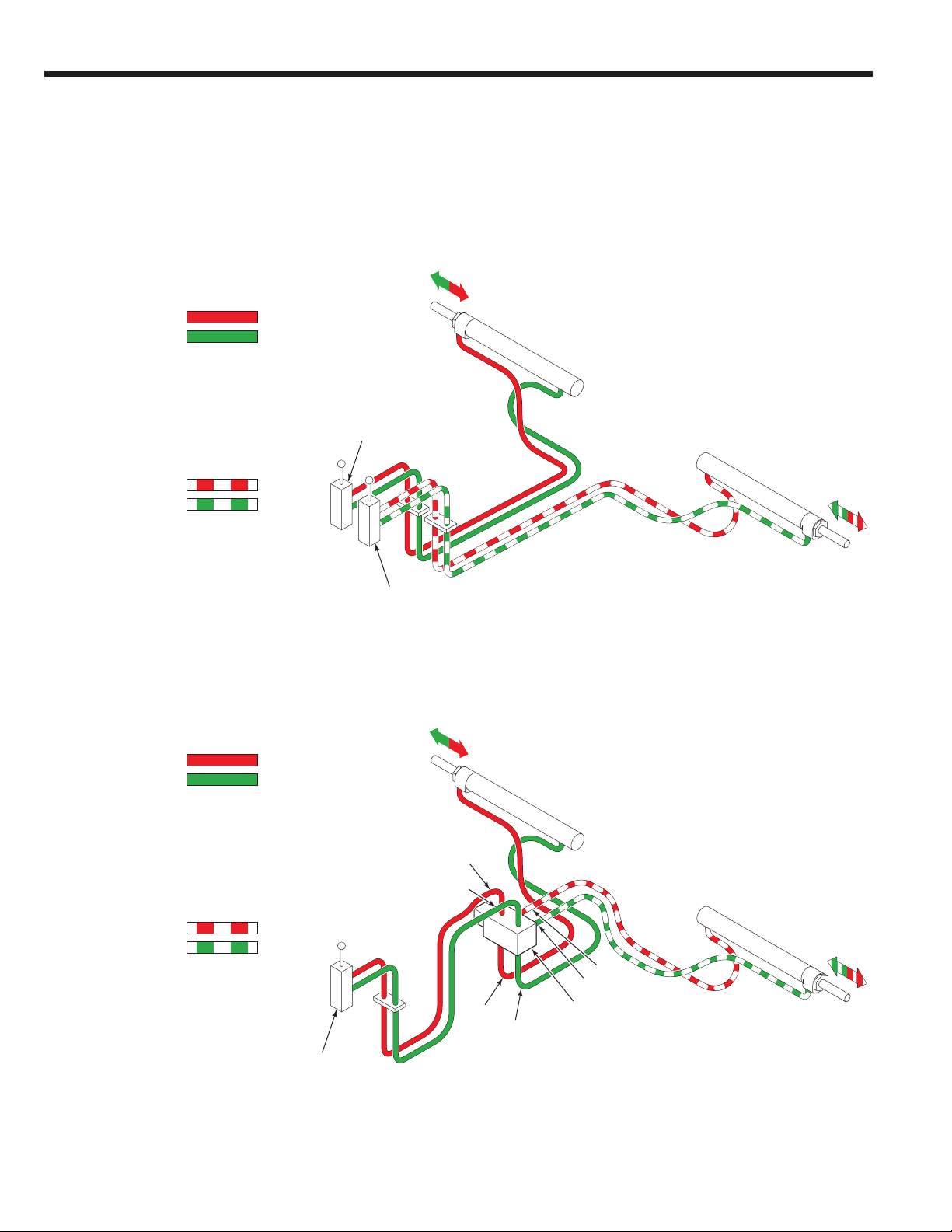
3.2-3 Hosing Diagram –
Simultaneous Open/Close
3.2-4 Hydraulic Schematic –
Simultaneous Open/Close
CLOSE FRAMES
PRESSURE
RETURN
NOTE: For OPEN FRAMES, reverse
the colors shown.
Left Frame
Sideshift Cylinder
Right Frame
Sideshift Cylinder
Flow Divider/
Combiner
OPEN/CLOSE
Truck Auxiliary Valve
Truck Relief Valve
Truck
Pump
Truck Tank
IHR Terminal
Left Frame
Sideshift Cylinder
Right Frame
Sideshift Cylinder
OPEN/CLOSE
Sideshift Frames
Truck Auxiliary Valve
Internal Hose Reeving
CL
OP
Attachment Valve
CL OP

TROUBLESHOOTING
76903351
SS1452.eps
3.2-5 Hosing Diagram – Simultaneous
Open/Close and Left/Right
CLOSE FRAMES
PRESSURE
RETURN
NOTE: For OPEN FRAMES, reverse
the colors shown.
SIDESHIFT FRAMES LEFT
PRESSURE
RETURN
SLAVE
NOTE: For SIDESHIFT FRAMES RIGHT,
reverse the colors shown.
Left Frame
Sideshift Cylinder
Left Frame
Sideshift Cylinder
Right Frame
Sideshift Cylinder
Right Frame
Sideshift Cylinder
Solenoid Valve
Equipped,
De-Energized
Solenoid Valve
Equipped,
Energized
Internal Hose Reeving
Internal Hose Reeving Internal Hose Reeving
Sideshift Frames
LEFT/RIGHT
Truck Auxiliary Valve
Truck
Auxiliary
Valve
Truck
Auxiliary
Valve
Sideshift Frames
LEFT/RIGHT
Truck Auxiliary Valve
T
T
P
P
CL
SSL
OP
SSR
C1
C2
C3
C4
OPEN/CLOSE
Sideshift Frames
Truck Auxiliary Valve
OPEN/CLOSE
Sideshift Frames
Truck Auxiliary Valve
1
1
2
2
1To Two Function Control Valve SSL/SSR
2To Two Function Control Valve OP/CL
1To Two Function Control Valve SSL/SSR
2To Two Function Control Valve OP/CL

86903351
TROUBLESHOOTING
T
1234
P
123234
14
12
34
SSL
CL OP
SSR
BA
BA
SS1453.eps
BA
Left Frame
Sideshift Cylinder
Right Frame
Sideshift Cylinder
Truck
Auxiliary
Valve
Truck Relief Valve Truck Relief Valve
Truck
Pump
Truck
Pump
Truck Tank Truck Tank
IHR Terminals IHR Terminal
1 2
Truck Auxiliary Valve:
1Sideshift Frames LEFT/RIGHT
2OPEN/CLOSE Sideshift Frames
One Truck Auxiliary Valve (Solenoid Equipped)Two Truck Auxiliary Valves
3.2-6 Hosing Schematic – Simultaneous
Open/Close and Left/Right
Check
Valves
Flow Divider/
Combiner
Attachment
Valve
Solenoid
Valve
Other manuals for F Series
1
Table of contents