Cardio Zone E-CZ300 User manual

315-00120
08/07 Rev A
SERIAL TAG IS LOCATED ON THE FRAME
Model Name: E-CZ300
Date of Purchase:
Serial Number:
Customer Service
(888) 340-0482
Manufactured By:
CardioZone Products
4009 Distribution Drive
Suite 250
Garland, TX 75041
Owner’s Manual
E-CZ300 Elliptical

2
Important Safety Information 3
Assembly 5
Console Instructions 12
Adjustment Instructions 18
Monitoring Your Heart Rate 19
Warm-Up Exercises 20
Troubleshooting 23
Parts List 24
Exploded Views 25
Warranty Information 26
Table of Contents

3
WARNING! Before using this unit or starting any exercise program, consult your physician.
This is especially important for persons over the age of 35 and/or persons with pre-existing
health problems. The manufacturer or distributor assumes no responsibility for personal injury
or property damage sustained by or through the use of this product.
WARNING! To reduce the risk of electrical shock, burns, fire, or other possible injuries to the
user, it is important to review this manual and the following precautions before operation.
SAFETY PRECAUTIONS AND TIPS
1. It is the owner's responsibility to ensure that all users of this unit have read the Owner's
Manual and are familiar with warnings and safety precautions.
2. This unit has a user maximum capacity of 300 pounds.
3. The unit should only be used on a level surface and is intended for indoor use only. The unit
should not be placed in a garage, patio, or near water and should never be used while you
are wet. CardioZone recommends a mat be placed under the unit to protect floor or carpet
and for easier cleaning.
4. Follow safety information in regards to plugging in your unit. Do not run the power cord
underneath your unit. Do not operate the unit with a damaged or frayed power cord.
5. Wear comfortable, good-quality walking or running shoes and appropriate clothing. Do not
use the unit with bare feet, sandals, socks or stockings.
6. Always examine your unit before using to ensure all parts are in working order.
7. Allow the unit to fully stop before dismounting.
8. Pets should never be allowed near the unit.
9. Do not leave children unsupervised near or on the unit.
10. Never operate the unit where oxygen is being administered, or where aerosol products are
being used.
11. Never insert any object or body parts into any opening.
12. For safety and to prevent damage to your unit, no more than one person should use the
unit at a time.
13. Always unplug the unit before cleaning and/or servicing. Service to your unit should only be
performed by an authorized service representative, unless authorized and/or instructed by
the manufacturer.
14. Failure to follow these instructions will void the unit warranty.
Important Safety Information

4
SAFETY PRECAUTIONS AND TIPS FOR CHEST STRAP
1. It is the owner's responsibility to ensure that all users of this unit have read the Owner's
Manual and are familiar with warnings and safety precautions.
2. Do not place chest strap near devices that generate large magnetic fields. TV sets, elec-
tric motors, radios, and high voltage power lines can affect the transmitter’s performance.
These items can interfere with the heart rate signal and possibly affect the heart rate read-
ings on the console.
3. Handle the chest strap with care. Dropping the transmitter might cause damage that could
void the warranty.
4. Do not use the chest strap if you have a cardiac pacemaker or if your are taking medications
for a heart condition. Medication or electrical pulses from the pacemaker can interfere with
accurate heart rate readings.
5. Do not bend the strips inside the chest strap. This can cause the chest strap to lose
conductivity.
6. The chest strap has batteries that need to be replaced periodically. A faulty battery can
cause an inaccurate reading.
Important Safety Information
5
Thank you for purchasing the CardioZone E-CZ300 Elliptical! The quality product you have
chosen was designed to meet your needs for cardiovascular exercise. Before you start, please
read the Owner’s Manual and become familiar with the operation of your new unit.
Remember to take time to perform stretching exercises, provided in this manual, to help avoid
injury.
If you are taking medication, consult your physician to see what effect the medication will have
on your exercise heart rate.
If you have heart problems, you are not active, and/or are over the age of 35 years, do not
use the pre-set programs or start an exercise program without first contacting and receiving
approval from your physician.
To avoid the risk of electrical shock, always keep the console dry. Do not spill liquids on the
console. CardioZone recommends a sealed water bottle for beverages consumed while using
the unit.
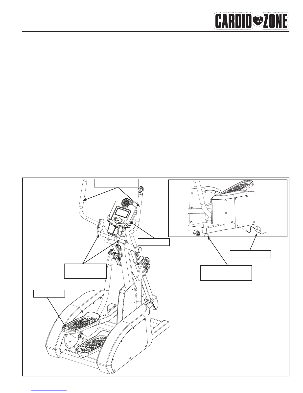
Please review the following drawing below to familiarize yourself with the listed
parts.
Important Safety Information
CONSOLE
AC ADAPTER
LEVELER FEET
2 PER SIDE
PEDALS
PULSE GRIP
HANDLEBARS
HANDLEBARS
6
Getting Started - The CardioZone E-CZ300 Elliptical will require some assembly. Unpack the
box in a clear area. Remove packing material. Do not dispose of packing material until assem-
bly is complete and unit is working properly. Place the unit on a clean level surface for assem-
bly. Make sure there is easy access to an electrical outlet. Before assembling, the unit should
be placed as close as possible to its final location. Locate all hardware bags, Labeled Figure
1 through Figure 9, with the exception of Figure 8. If you are missing any bags, please call
CardioZone at 1-888-340-0482. Tools have been provided to assist with product assembly.
Assembly
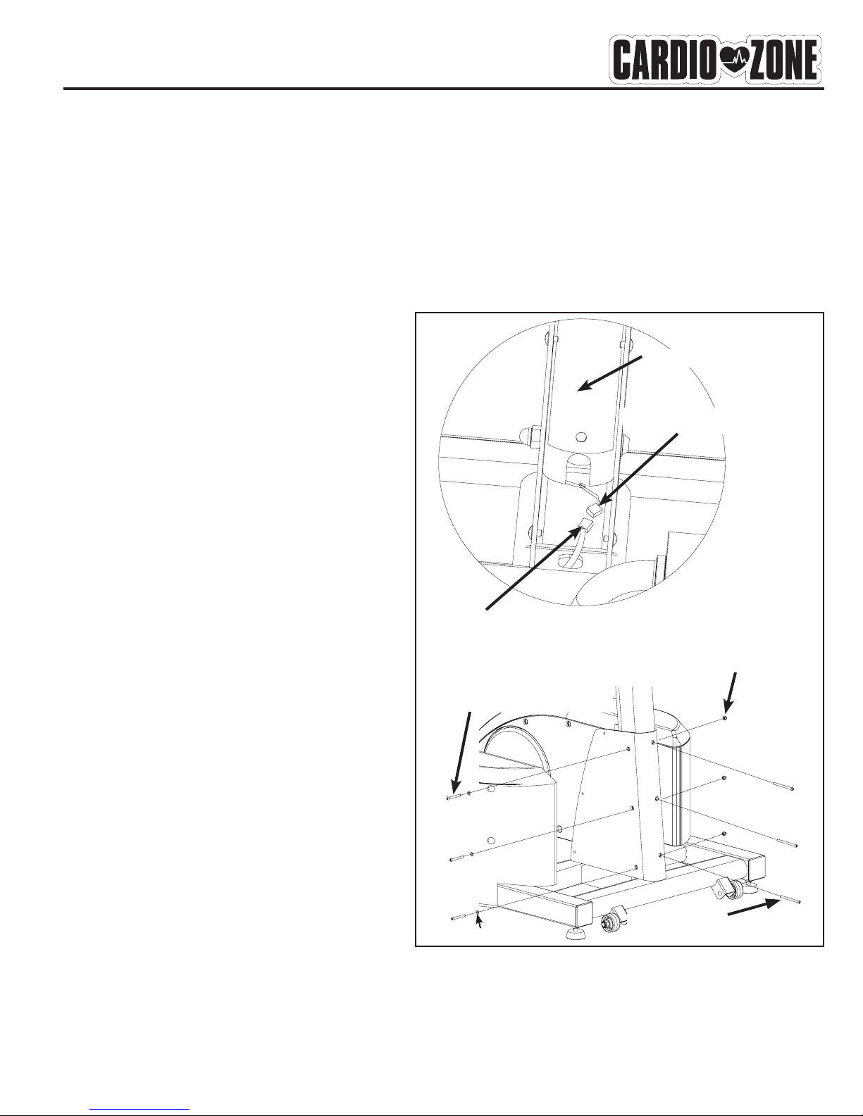
Figure 1
Locate bag labeled Figure 1. Locate
console tube. Attach console tube to
main frame. Slide tube down into main
frame. Connect upper console wire to
lead wire assembly. Secure using three
M10*80 mm hex head screws extend-
ing through the frame and console tube,
three 10*20 washers and three crown
nuts, M10*1.5. Use three M10*120 hex
screws to secure through the front of the
console tube and main frame.
Note: Ensure that all wires are secure
inside console. Be careful not to pinch
wires.
Figure 1
M10*80 HEX SCREW
CROWN NUT, M10*1.5
M10*120 HEX SCREW
UPPER CONSOLE WIRE
LEAD WIRE ASSEMBLY
CONSOLE TUBE
10*20 WASHER
7
Assembly
Figure 2
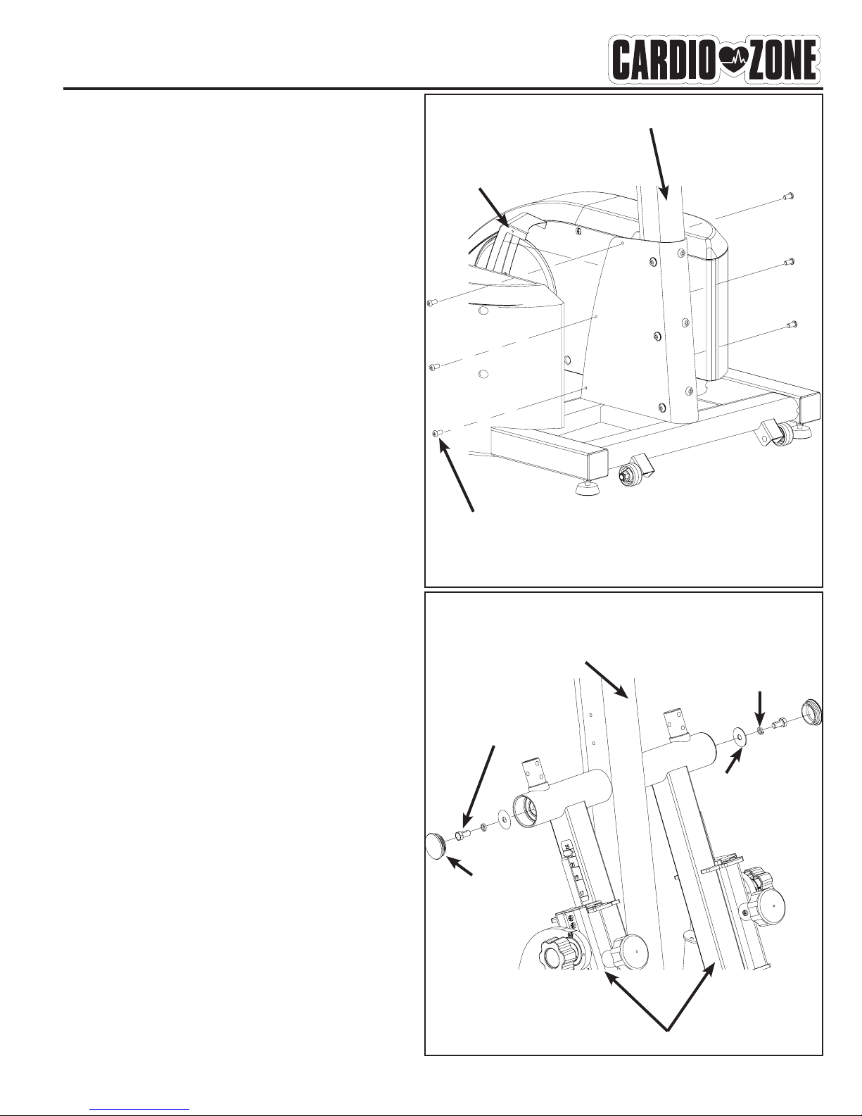
Locate bag labeled Figure 2. Locate cover.
Secure cover to main frame by using three
M5*0.8-12 screws on the left side of unit.
Repeat for the right side.
Figure 2
Figure 3
Locate bag labeled Figure 3. Locate left
and right handrail assemblies. Secure left
handrail assembly to console tube by using
one washer, one spring washer, one M10*20
hex bolt, and one end cap. Repeat for the
right side.
Note: The handrail assembly will only
go onto the console tube one way. The
connector on the middle of the handrail
assembly will face outwards.
Figure 3
M5*0.8-12 SCREW
END CAP
M10*20, HEX BOLT
SPRING WASHER
WASHER
CONSOLE TUBE
HANDRAIL ASSEMBLY
CONSOLE TUBE
COVER

8
Assembly
Figure 5
Locate bag labeled Figure 5. Locate right
pedal tube assembly. Secure pedal tube
assembly to the handrail assembly with
one M10*81.5 hex bolt and one M10*1.5
hex nut. Please ensure that pedal arm is
aligned in the center of roller wheel while
tightening M10*81.5 bolt (Figure 5a).
Repeat for the left side.
Note: It is recommended that 2 adults
align and secure the pedal tube assemblies
to the handrail assemblies.
Figure 4
Locate bag labeled Figure 4. Lift and
place left linkage onto shaft sleeve and align
holes. Secure linkage to unit using four
M8*12 mm hex bolts. Repeat for right side.
Note: The linkage is secured to the sleeve
with three M8*12 hex bolts on the top of
the linkage and one M8*12 hex bolt on the
bottom of the linkage.
Figure 4
Figure 5
M8*12 HEX BOLT
M10*81.5 HEX BOLT
M10*1.5 HEX NUT
SLEEVE
LINKAGE
HANDRAIL ASSEMBLY
PEDAL TUBE ASSEMBLY
Figure 5a
9
Assembly
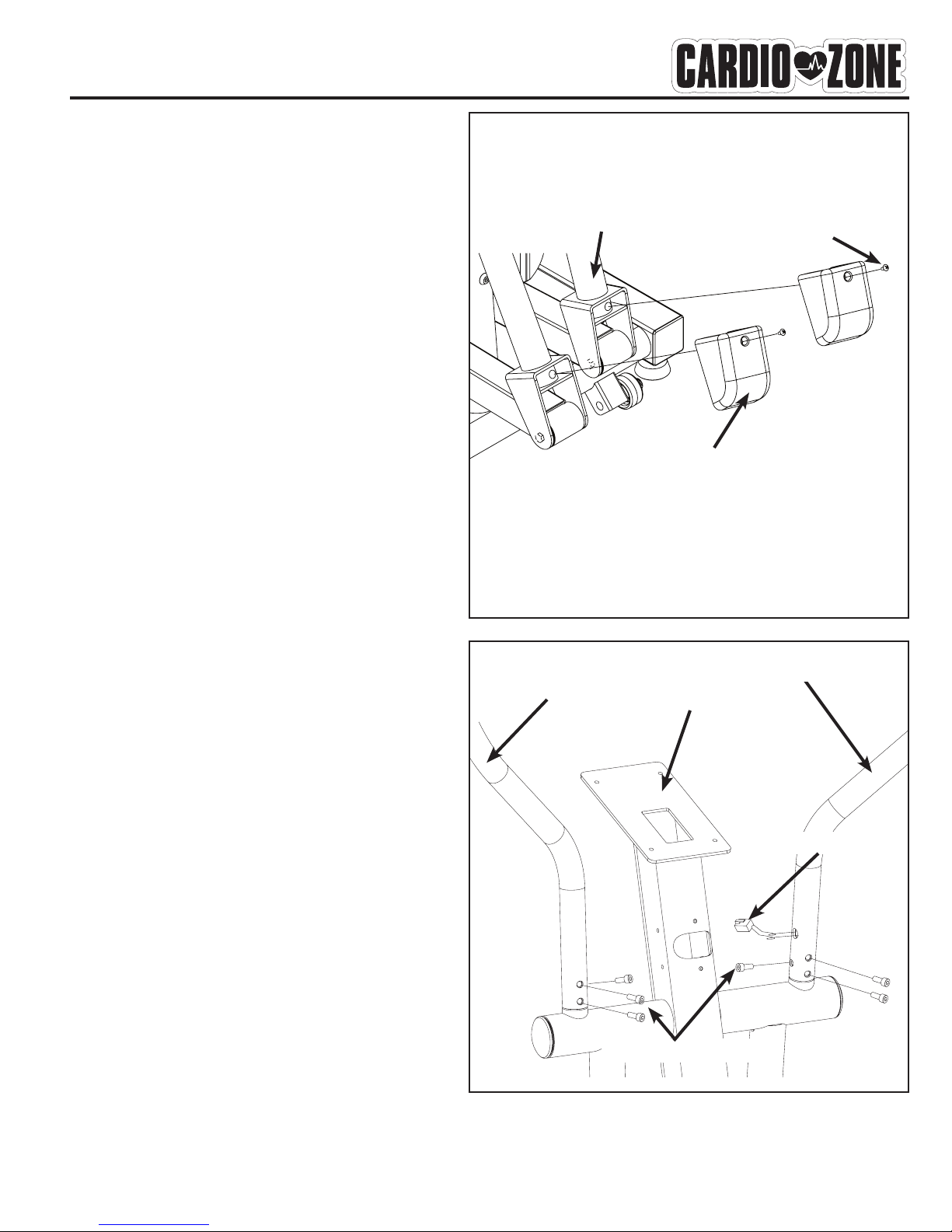
Figure 6
Locate bag labeled Figure 6. Locate
bracket covers. Attach bracket cover to
the handrail assembly by lining up hole,
and securing using one screw, M5*0.8-12.
Repeat for other side.
Note: Do not overtighten screw, this will
damage bracket cover.
Figure 6
Figure 7
Locate bag labeled Figure 7. Locate han-
dlebars. Attach left handlbar to handlebar
assembly using three M8*16mm hex bolts.
Repeat for other handlebar. Ensure that
toggle wire is not pinched and moved out of
the way.
Figure 7
BRACKET COVER
M5*0.8-12 SCREW
LEFT HANDLEBAR
M8*16 HEX BOLT
RIGHT HANDLEBAR
CONSOLE TUBE
HANDRAIL ASSEMBLY
TOGGLE WIRE
10
Assembly
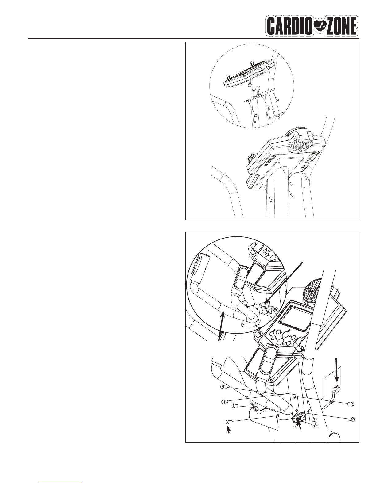
Figure 9
Locate bag labeled Figure 9. Connect the
pulse wires coming from the pulse handle-
bar assembly to the pulse wires from the
console. Secure pulse handlebar assembly
to console tube using six M6*10 hex socket
head bolts. Insert toggle wire into the tog-
gle jack located on the console tube.
Note: Ensure that all wires are secure
inside console tube. Be careful not to pinch
wires.
Figure 9
Figure 8
Locate Console. Connect upper console
wire and pulse wires to the appropriate
location on the back of the console. Secure
console to console tube using four screws.
Note: The four console screws will already
be installed into the back of console when
you remove it from the box.
Figure 8
M6*10 HEX SOCKET BOLT
PULSE WIRE
TOGGLE WIRE
TOGGLE WIRE
JACK
PULSE HANDLEBAR
ASSEMBLY
Table of contents
Other Cardio Zone Elliptical Trainer manuals

Popular Elliptical Trainer manuals by other brands


Bonn Germany
Bonn Germany Concept 2.2 user manual

Precor
Precor Resolute RSL 620 Assembly guide

NordicTrack
NordicTrack E 9.2 Elliptical HASZNALATI UTASITAS

Vision Fitness
Vision Fitness X6600iNetTV Assembly guide

Matrix
Matrix MX-A5x owner's manual

SportsArt Fitness
SportsArt Fitness ECO-NATURAL Elite E874 owner's manual


