CAME BXL04AGS User manual

Sliding-gate operators
BXL04AGS BXL04ALS
INSTALLATION MANUAL
FA01947-EN
EN
Italiano

Page 2- Manual FA01947-EN - 03/2023 - © CAME S.p.A. - The contents of this manual may be changed at any time and without notice. - Translation of the original instructions
1
2
3
4
3
2
1

Page 3- Manual FA01947-EN - 03/2023 - © CAME S.p.A. - The contents of this manual may be changed at any time and without notice. - Translation of the original instructions
GENERAL PRECAUTIONS FOR INSTALLERS
Important safety instructions.
Please follow all of these instructions. Improper installation may cause serious bodily harm.
Before continuing, please also read the general precautions for users.
Only use this product for its intended purpose. Any other use is hazardous. • The manufacturer cannot be held liable for any
damage caused by improper, unreasonable or erroneous use. • This product is defined by the Machinery Directive (2006/42/EC)
as partly completed machinery. • Partly completed machinery means an assembly which is almost machinery but which cannot
in itself perform a specific application. • Partly completed machinery is only intended to be incorporated into or assembled with
other machinery or other partly completed machinery or equipment thereby forming machinery to which the Machinery Directive
(2006/42/EC) applies. • The final installation must comply with the Machinery Directive (2006/42/EC) and the European reference
standards in force. • The manufacturer declines any liability for using non-original products, which would also void the warranty.
• All operations indicated in this manual must be carried out exclusively by skilled and qualified personnel and in full compliance
with the regulations in force. • The device must be installed, wired, connected and tested according to good professional practice,
in compliance with the standards and laws in force. • Make sure the mains power supply is disconnected during all installation
procedures. • Check that the temperature ranges given are suitable for the installation site. • Do not install on slopes i.e. any
surfaces that are not perfectly level. • Do not install the operator on surfaces that could yield and bend. If necessary, add suitable
reinforcements to the anchoring points. • Make sure that no direct jets of water can wet the product at the installation site
(sprinklers, water cleaners, etc.). • Make sure you have set up a suitable dual-pole cut-off device along the power supply that is
compliant with the installation rules. It should completely cut off the power supply according to category III surcharge conditions.
• Demarcate the entire site properly to prevent unauthorised personnel from entering, especially minors. • In case of manual
handling, have one person for every 20 kg that needs hoisting; for non-manual handling, use proper hoisting equipment in safe
conditions. • Use suitable protection to prevent any mechanical hazards due to persons loitering within the operating range of the
operator. • The electrical cables must pass through special pipes, ducts and cable glands in order to guarantee adequate protection
against mechanical damage. • The electrical cables must not touch any parts that may overheat during use (such as the motor
and transformer). • Before installation, check that the guided part is in good mechanical condition, and that it opens and closes
correctly. • The product cannot be used to automate any guided part that includes a pedestrian gate, unless it can only be enabled
when the pedestrian gate is secured. • Make sure that nobody can become trapped between the guided and fixed parts, when the
guided part is set in motion. • Use additional protection to prevent your fingers from being crushed between the pinion and rack. •
All fixed controls must be clearly visible after installation, in a position that allows the guided part to be directly visible, but far away
from moving parts. In the case of a hold-to-run control, this must be installed at a minimum height of 1.5 m from the ground and
must not be accessible to the public. • If not already present, apply a permanent tag that describes how to use the manual release
mechanism close to it. • Make sure that the operator has been properly adjusted and that the safety and protection devices and the
manual release are working properly. • Before handing over to the final user, check that the system complies with the harmonised
standards and the essential requirements of the Machinery Directive (2006/42/EC). • Any residual risks must be indicated clearly
with proper signage affixed in visible areas, and explained to end users. • Put the machine’s ID plate in a visible place when the
installation is complete. • If the power supply cable is damaged, it must be immediately replaced by the manufacturer or by an
authorised technical support service, or in any case, by qualified staff, to prevent any risk. • Keep this manual inside the technical
folder along with the manuals of all the other devices used for your automation system. • Make sure to hand over to the end user
all the operating manuals of the products that make up the final machinery. • The product, in its original packaging supplied by
the manufacturer, must only be transported in a closed environment (railway carriage, containers, closed vehicles). • If the product
malfunctions, stop using it and contact customer services at https://www.came.com/global/en/contact-us or via the telephone
number on the website. • The manufacture date is provided in the production batch printed on the product label. If necessary,
contact us at https://www.came.com/global/en/contact-us. • The general conditions of sale are given in the official CAME price
lists.

Page 4- Manual FA01947-EN - 03/2023 - © CAME S.p.A. - The contents of this manual may be changed at any time and without notice. - Translation of the original instructions
Main points of danger for people
No transiting while the barrier is moving.
Risk of entrapment.
Risk of trapping hands.
Risk of trapping feet.
DISMANTLING AND DISPOSAL
CAME S.p.A. employs an Environmental Management System at its premises. This system is certified and compliant with the UNI EN ISO 14001 standard to ensure
that the environment is respected and safeguarded. Please continue safeguarding the environment. At CAME we consider it one of the fundamentals of our operating and
market strategies. Please follow these brief disposal guidelines:
DISPOSING OF THE PACKAGING
The packaging materials (cardboard, plastic, etc.) can be disposed of easily as solid urban waste, separated for recycling.
Before dismantling and disposing of the product, please always check the local laws in force.
DISPOSE OF THE PRODUCT RESPONSIBLY.
DISPOSING OF THE PRODUCT
Our products are made of various materials. Most of these materials (aluminium, plastic, iron and electrical cables) are classified as solid urban waste. They can be
separated for recycling and disposed of at authorised waste treatment plants.
Other components (electronic boards, transmitter batteries, etc.) may contain pollutants.
These must be removed and disposed of by an authorised waste disposal and recycling firm.
It is always advisable to check the specific laws that apply in your area.
DISPOSE OF THE PRODUCT RESPONSIBLY.

Page 5- Manual FA01947-EN - 03/2023 - © CAME S.p.A. - The contents of this manual may be changed at any time and without notice. - Translation of the original instructions
PRODUCT DATA AND INFORMATION
Key
This symbol shows which parts to read carefully.
This symbol shows which parts describe safety issues.
This symbol shows what to tell users.
The measurements, unless otherwise stated, are in millimetres.
Description
801MS-0140
BXL04AGS - Operator with 24 V motor, featuring a control board with DIP switch settings, on-board radio decoding, movement and obstruction detecting device for sliding
gates weighing up to 400 kg that are up to 10 m long. RAL7024 grey cover.
801MS-0141
BXL04ALS - Operator with 24 V motor, featuring a control board with DIP switch settings, on-board radio decoding, movement and obstruction detecting device for gates
weighing up to 400 kg that are up to 10 m long. RAL7040 grey cover.
Intended use
Sliding gate solution for residential buildings and apartment blocks
Any installation and/or use other than that specified in this manual is forbidden.

Page 6- Manual FA01947-EN - 03/2023 - © CAME S.p.A. - The contents of this manual may be changed at any time and without notice. - Translation of the original instructions
Description of parts
Operator
1
Cover
2
Board-holder support
3
Gearmotor
4
Anchoring plate
5
Screws UNI5739 12X60
6
Washer Ø 12
7
Nut UNI5588 M12
8
Board protection cover
9
Control board
10
Control board holder
11
Release lever
12
Lock
13
Mechanical limit-switch tabs
14
EMC02 control board
15
Transformer
16
Mechanical limit switch
17
Release key
8
10
1
15
16 7
6
1
9
11
12
3
7
6
2
14
4
13
17
4
5

Page 7- Manual FA01947-EN - 03/2023 - © CAME S.p.A. - The contents of this manual may be changed at any time and without notice. - Translation of the original instructions
Control board
Before working on the control panel, disconnect the mains power supply and remove the batteries, if any.
Use DIP switches to set functions and the trimmer for adjustments.
All connections are protected by quick fuses.
For the system to work properly, before fitting any plug-in card, DISCONNECT THE MAIN POWER SUPPLY and remove any batteries.
1
DIP switches
2
Trimmer
3
Button for programming
4
Alert LED
5
Control button
6
Terminal board for encoders and limit switches
7
Terminal board for connecting control and safety devices
8
Terminal board for connecting the keypad selector
9
Terminal board for connecting the gearmotor
10
Terminal board for powering accessories
11
Terminal board for powering the control board
12
Fuse for accessories and control board
13
Terminal board for connecting the antenna
14
Connector for plug-in radio frequency card (AF)
15
Terminal board for Green Power module
16
Component for R800 card
17
Power supply terminal board
18
Line fuse
12345
16
14
15
11
12
6
9
10
7
8
13
17
18
Remove the card cover before inserting the cards into the connectors.
OK

Page 8- Manual FA01947-EN - 03/2023 - © CAME S.p.A. - The contents of this manual may be changed at any time and without notice. - Translation of the original instructions
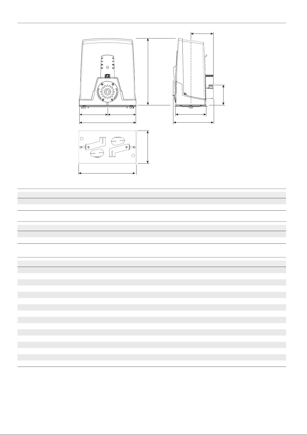
Size
117
211
349
105
160
300
170
298
149 149
Usage limitations
MODELS BXL04AGS BXL04ALS
Maximum gate-leaf length (m) 10 10
Maximum gate-leaf weight (kg) 400 400
Fuse table
MODELS BXL04AGS BXL04ALS
Line fuse 1.6 A-F -
Accessory fuse 2 A-F -
Technical data
MODELS BXL04AGS BXL04ALS
Power supply (V - 50/60 Hz) 230 AC 230 AC
Motor power supply (V) 24 DC 24 DC
Standby consumption (W) 5,5 5,5
Power (W) 170 170
Maximum current draw (A) 7 7
Colour RAL 7024 RAL 7024
Operating temperature (°C) -20 ÷ +55 -20 ÷ +55
Thrust (N) 350 350
Manoeuvring speed (m/min) 12 12
Duty cycle 50 50
Pinion module 44
Protection rating (IP) 44 44
Insulation class I-
Weight (kg) 7,7 -
Storage temperature (°C) * -20 ÷ +70 -
Average life (hours) ** 120000 -
(*) Before installing the product, keep it at room temperature where it has previously been stored or transported at a very high or very low temperature.
(**) The average product life is a purely indicative estimate. It applies to compliant usage, installation and maintenance conditions. It is also influenced by other
factors, such as climatic and environmental conditions.

Page 9- Manual FA01947-EN - 03/2023 - © CAME S.p.A. - The contents of this manual may be changed at any time and without notice. - Translation of the original instructions
Cable types and minimum thicknesses
Cable length (m) up to 20 from 20 to 30
Power supply 230 V AC 3G x 1.5 mm2 3G x 2.5 mm2
24 V AC/DC flashing beacon 2 x 0.5 mm2 2 x 0.5 mm2
TX Photocells 2 x 0.5 mm2 2 x 0.5 mm2
RX photocells 2 x 0.5 mm2 2 x 0.5 mm2
Command and control devices * no. x 0.5 mm2 * no. x 0.5 mm2
* no. = see product assembly instructions - Warning: the cable cross-section is indicative and varies according to the motor power and cable length.
When operating at 230 V and outdoors, use H05RN-F cables compliant with 60245 IEC 57 (IEC); when indoors, use H05VV-F cables compliant with 60227 IEC 53
(IEC). For power supplies up to 48 V, use FROR 20-22 II cables compliant with standard EN 50267-2-1 (CEI).
To connect the antenna, use RG58 cable (up to 5 m).
For paired connection and CRP, use UTP CAT5 cable (up to 1,000 m).
If the cable lengths differ from those specified in the table, define the cable cross-sections according to the actual power draw of the connected devices and in
line with regulation CEI EN 60204-1.
For multiple, sequential loads along the same line, recalculate the values in the table according to the actual power draw and distances. For information on
connecting products not covered in this manual, please see the documentation accompanying the products themselves.

Page 10 - Manual FA01947-EN - 03/2023 - © CAME S.p.A. - The contents of this manual may be changed at any time and without notice. - Translation of the original instructions
INSTALLATION
The following illustrations are examples only. The space available for fitting the operator and accessories varies depending on the area where it is installed. It is
up to the installer to find the most suitable solution.
The drawings show an operator fitted on the left.
Preliminary operations
Dig a hole for the foundation frame.
Set up the corrugated tubes needed for the wiring coming out of the junction pit.
Use Ø 40 mm corrugated tubes to connect the gearmotor to the accessories.
The number of tubes depends on the type of system and the accessories that are going to be fitted.
300
450
400
Laying the anchoring plate
Set up a foundation frame that is larger than the anchoring plate.
Insert the foundation frame into the dug hole.
The foundation frame must protrude by 50 mm, above ground level.
Fit an iron cage in the foundation frame to reinforce the concrete.
50
Other manuals for BXL04AGS
1
This manual suits for next models
1
Table of contents
Other CAME Gate Opener manuals
Popular Gate Opener manuals by other brands

SOMFY
SOMFY Dexxo RTS Pro INSTALLATION INSTRUCTIONS-ILLUSTRATIONS

Cardin
Cardin BL Series manual

Westfalia
Westfalia 85 27 06 instruction manual

Extel
Extel VERA quick guide

Comunello Automation
Comunello Automation ABACUS 220 Installation and user manual

Mighty Mule
Mighty Mule 200 E-Z GATE OPENER UL325 SERIES installation manual