Cable-Tronix CT-SAW860 User manual

INSTALLATION MANUAL
CT-SAW860
Audio/Video Modulator
1

PACKAGE CONTENTS
This package contains:
One CT-SAW860SAW-Filtered Audio/Video Modulator
One CT-SAW860 Installation Manual
PRODUCT DESCRIPTION
The CT-SAW860 is an all solid-state audio/video modulator that provides a modulated video and
aural RF carrier output on a fixed channel from 54MHz to 860MHz. The modulator accepts
standard polarity video at a 0.7-2.5 Vp-p level from video sources such as a satellite receiver,
demodulator, TV camera, DVD player or video tape recorder. The unit provides high quality
video, color, and audio signals on any unused channel within a closed circuit MATV, SMATV, or
CATV system. For easy operation, all level controls are located on the front panel.
2

SPECIFICATIONS
CT-SAW860
SAW-Filtered Audio/Video Modulator Specifications (Typical)
RF
1.Output Channels TV VHF: 2-13, UHF: 14-69, CATV: 2-127
2.Output Level +55 dBmV (minimum)
.Output Level Range 13 dB
4.A/V Carrier Ratio -7dB to -22dB
5.Spurious Output -60 dB below video carrier (@A/V carrier ration -15 dB)
6.Frequency Accuracy/Stability ±5 KHz
7.Output Impedance 75 Ohms
8.Output Return Loss 9 dB
VIDEO
1.Video Input Level 0.5 Vp-p minimum @87.5% Modulation
2.Differential Gain <5% (10 to 90% APL)
3.Differential Phase <5˚(10 to 90% APL)
4.Hum and Noise -60 dB @87.5% Modulation
5.Visual Carrier to Noise Ratio 60 dB @4 MHz BW
6.Frequency Response ±0.8 dB (30 Hz to 4.2 MHz)
AUDIO
1.Input Level 0.5 Vp-p for ±25 KHz Deviation
2.Input Impedance 600 Ohms Unbalanced
3.Pre-Emphasis 75 µSec
GENERAL
1.Power Input Range 120 VAC, 60 Hz
2.Operating Temperature 32 ˚F ~ 122 ˚F
3.Connectors All "F" Type
MECHANICAL
1.Dimensions 19" (W) x 1.75" (H) x 2.25" (D)
2.Weight 4.3 lbs
INSTALLATION AND OPERATION
NOTE TO SYSTEM INSTALLER
System installer must adhere to Article 820-40 of the NEC that
provides guidelines for proper grounding and specifies that the
cable ground shall be connected to the grounding system of the
building, as close to the point of cable entry as practical.
3

1. UNPACKING and HANDLING
Each unit is shipped with all equipment assembled, and factory tested.
Ensure that all accessories are removed from the container before discarding packing
material
2. MECHANICAL INSPECTION
Inspect the front and rear of the equipment for shipping damage. Make sure the equipment is
clean, and no connectors are broken, damaged, or loose. If equipment appears to be
damaged or defective please contact us at 1-610-429-1511 for assistance.
3. PRODUCT DIAGRAM
cdefghi
jkl11 12
1 Power “Power-On” indicator light
2 Channel Preset Channel
3 Output Test The input signal is tapped down –30dB for monitoring.
Test port must be terminated when not in use
4 Output Level Simultaneously adjusts amplitude of aural and visual
carriers
5 Audio Level Adjusts for 25KHz peak deviation
6 Aural Level Controls amplitude of aural RF carrier to change
aural/video ratio
7 Video Level Adjusts depth of modulation when video level is greater
than 1.5Vp-p terminated signal
8 Video Input F-connector accepts a video signal from a source such
as a satellite receiver, demodulator, or DVD player
9 Audio Input F-connector accepts audio signal from a video source
such as a satellite receiver, demodulator, or DVD player
10 RF Output The modulated output signal is available for distribution
from the F-connector
11 Convenience Outlet Allows looping of power among units
12 Power Cord For 120VAC, 60Hz
4

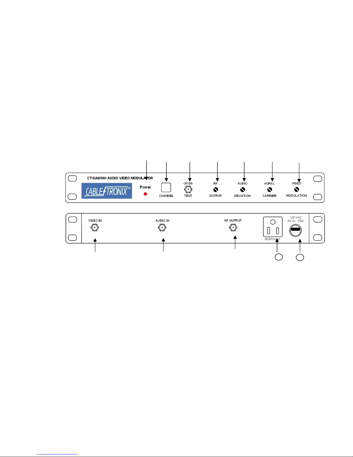
4. HARDWARE CONNECTIONS
a. The CT-SAW860 is designed for installation in a standard 19” ELA rack.
b. Connect a 75ohm coaxial cable with F-connectors from the video source’s Audio
Output port to the CT-SAW860’s Audio Input port.
c. Connect a 75ohm coaxial cable with F-connectors from the video source’s Video
Output port to the CT-SAW860’s Video Input port.
d. Connect a 75ohm coaxial cable with F-connectors from the CT-SAW860’s RF Output
port to the headend combiner.
e. Connect the CT-SAW860 to an appropriate power source capable of powering this
device. Be certain that power source is capable of handling the load if the CT-
SAW860 and other equipment are being powered by it.
5. CHANNEL SELECTION
The CT-SAW860 is a fixed frequency modulator and units are pre-programmed for a single
given channel at the factory. No channel selection is available from the unit.
6. ADJUSTMENT
a. After installation and completing all hardware connections power the unit and wait 20
minutes before making the following adjustments.
b. For testing purposes no more than 15dB from the RF Output should be going to a
TV or RF input monitor. Use an attenuator to reduce the signal level if testing with an
RF Input monitor. Individual CT-SAW860 setup and level settings can be tested from
the RF Output port. However, system level testing should be done from the
combiner.
c. With a nominal 1 Vp-p video source connected, adjust the VIDEO LEVEL control fully
clockwise. The circuit will automatically set the unit for 87.5% modulation over an
input level of 0.5 to 1.5 volts peak-to-peak. If the video input is greater than 1.5Vp-p,
adjust the VIDEO LEVEL for correct percentage of modulation (87.5%). If test
equipment is not available then adjust for proper picture contrast when viewed on a
TV monitor and compare with known Off-Air broadcast picture quality.
d. With audio source connected, adjust AUDIO LEVEL control on the front panel for 25
KHz deviation. Instead of an audio modulation meter, use a TV set and adjust for
equal volume as compared to a known Off-Air broadcast. Monitor for a few minutes
to assure the maximum volume does not over modulate, which can cause picture
distortion.
e. During field maintenance of the headend the CT-SAW860’s Output Test port can be
used for taking unit measurements. However, note the output from the port is
padded down -30 dB and must be taken into consideration when adjusting levels.
5

8. TROUBLESHOOTING
a. Ensure you are using quality multiple shielded cables with quality radial or
compression F-connectors.
b. Ensure the F-connector’s center conductor is making solid contact with the C-
SAW860’s Video Input, Audio Input, and RF Output ports.
c. If the CT-SAW860 is receiving power but no signal, check to be sure the video and/or
audio input cables are securely connected with their respective Video Output and
Audio Output ports on the video source and the Video Input and Audio Input ports on
the CT-SAW860. Also ensure the cable is securely connected at the CT-SAW860’s
RF Output port and the combiner’s input ports.
d. When taking measurements it is always best to use a quality signal level meter. For
initial individual CT-SAW860 setup measurements may be taken from the unit’s RF
Output port. System level measurements, however, should be taken from the
combiner’s output. For field maintenance, the CT-SAW860’s Output Test port may
be used. However, note that port is padded down -30dB that must be taken into
consideration when determining individual unit level settings and output.
e. Further troubleshooting assistance can be found on-line at
www.northamericancable.com and www.cabletronix.com in addition to support from
Cabletronix sales engineers at 1-610-429-1511.
This is a notice to inform you that content passing thru this device may contain
strong language or depictions of violence, sex or substance abuse. This unit contains
no parental control features. Parental discretion is advised
6
Table of contents
Other Cable-Tronix Modulator manuals

Cable-Tronix
Cable-Tronix CTARM-2SV User manual

Cable-Tronix
Cable-Tronix CTADM-806 User manual

Cable-Tronix
Cable-Tronix CT-FMM User manual

Cable-Tronix
Cable-Tronix CT-SAMM User manual

Cable-Tronix
Cable-Tronix CTARM-2LTIR User manual

Cable-Tronix
Cable-Tronix CTARM IR Series User manual

Cable-Tronix
Cable-Tronix CTADM-806a User manual

Cable-Tronix
Cable-Tronix CT-FSAM550 User manual


