Brinly PRC-241BH User manual

1
Call Customer Service, Toll-Free: 877-728-8224
Important: This manual contains information for the safety
of persons and property. Read it carefully before
assembly and operation of the equipment!
Visit us on the web!
www.brinly.com
L-1681BH-M
English Manual
LAWN ROLLER
ROLLER MODELS:
PRC-241BH
PRC-241BH-A
PRT-361BH
PRT-361BH-A
PRT-361SBH
PRT-361SBH-A
PRT-481SBH
PRT-481SBHC-A
OWNER'S MANUAL
• Safety
• Assembly
• Operation
• Repair Parts
• Maintenance For use with Riders, Lawn or Garden Tractors and ATV’s
*PRC-241 BH Push version not shown.
English, Spanish &
French Manual

2L-1681BH-MEnglish Manual
INTRODUCTION AND SAFETY
SAFETY
=============================================
RULES FOR SAFE OPERATION
• Know controls and how to stop safely, READ THE OWNER’S
MANUAL before operating.
• Do not allow children to operate the vehicle, do not allow adults
to operate without proper instruction or without having read the
owner’s manual.
• Do not carry passengers. Keep children and pets a safe
distance away.
• Always wear substantial footwear. Do not wear loose tting clothing.
Do not wear loose tting clothing that can get caught in moving
parts.
• Keep your eyes and mind on your tractor / attachment and area
being covered. Do not let other interests distract you.
• Stay alert for holes in the terrain and other hidden hazards.
• Do not drive close to creeks, ditches and public highways.
• Watch out for trac when crossing or near roadways.
• When using any attachment, don’t allow anyone near the vehicle
while in operation.
• Keep the vehicle and attachment in good operating condition
and keep safety devices in place.
• Keep all nuts, bolts and screws tight to be sure the equipment
is in safe working condition.
• The vehicle and attachment should be stopped and inspected for
damage after striking a foreign object. The damage should be
repaired before restarting and operating the equipment.
• See tractor equipment owner’s manual for safe operation of the
equipment.
CUSTOMER RESPONSIBILITIES
- Please read & retain this manual. The instructions will enable to assemble and maintain your product properly.
- Please carefully read and observe the SAFETY SECTION of this manual.
- Follow a regular schedule in maintaining and caring for your Brinly-Hardy product.
CONGRATULATIONS on your new Brinly-Hardy Lawn Roller! This accessory has been designed, engineered and manufactured
to give you the best possible dependability and performance.
Should you experience any problem you cannot easily remedy, please do not hesitate to contact our knowledgeable customer
service department toll-free at 1-877-728-8224. We have competent, well trained technicians to help you with the assembly
and use of your Roller.
This symbol will help to point out important safety
precautions throughout this manual. It means -
ATTENTION! BECOME ALERT! Your safety is involved.
Tools Required
for Assembly:
• (x2) 1/2” Wrench
• (x2) 3/4” Wrench (PRC-241 BH Only)
• Slip Joint Pliers
TABLE OF CONTENTS
Safety ........................ 2
Hardware Identifier
and Part List .................. 3 - 5
Assembly ................... 6 - 10
Operation ...................... 11
Maintenance ................... 11
Warranty ......................12
3L-1681BH-M
English Manual
DO NOT RETURN PRODUCT IF YOU ARE MISSING PARTS.
Please Call: 1 (877) 728-8224
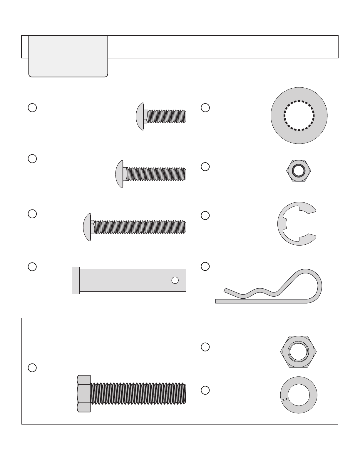
HARDWARE IDENTIFIER
Carriage Bolt
5/16 x 1”
(x4) . . . . . . . . . . . . . . . . . . . . . .
11M1016P
4
Carriage Bolt
5/16 x 1 1/2”
(x2) . . . . . . . . . . . . . . . .
11M1024P
5
Carriage Bolt
5/16 x 2 1/4”
(x2) . . . . . . .
11M1036P
6
Washer: Flat
5/8” (x4) . . . . . . .
45M2121P
7
Hitch Pin Cotter
(x1) . . . . . . . . . . . . . . . . .
14
D-146P
Hitch
Pin (x1)
. . . . . . . .
13
B-3861
Nut: Nylon Lock
5/16” (x8) . . . . . . . . . . .
8
B-4786
E-Ring, 5/8”
(x2) . . . . . . . . . . . . . .
11
F-577
PARTS IN ADDITIONAL HARDWARE BAG
(Only for PRC-241 BH)
Bolt: Hex Head
1/2 x 2-1/4”
(x1) . . . .
16
1M1636P
Nut: Hex
1/2” (x1) . . . . . . . . . .
17
30M1600P
Lock Washer 1/2”
(x1) . . . . . . . . . . . . . .
18
40M1600P
Illustrations on this page
are to scale for faster
identication of hardware
during assembly.
4L-1681BH-MEnglish Manual
PARTS
1
2
3
4
5
6
7
8
9
10
11
12
13
14
15
16
17
18
19
20
Frame Extension Bar 2
Roller Drum Assembly 1
Scraper Bar 1
5/16” x 1”, Carriage Bolt 4
5/16” x 1-1/2”, Carriage Bolt 2
5/16” x 2-1/4”, Carriage Bolt 2
5/8” Flat Washer 4
5/16” Nylon Lock Nut 8
Plug 1
Square Bearing 2
5/8” E-Ring 2
Frame Spacer 1
Hitch Pin 1
Hitch Pin Cotter 1
Handle 1
Hex Bolt 1/2” x 2-1/4 1
Hex Nut 1/2” 1
Lock Washer 1/2” 1
Grip 2
Clevis 2
Description Qty.Ref. #
5
21
31
20
14
9
3
2
1
4
6
11
01
8
7
7
8
8
7
7
11
01
16
15
19
18
17
B-3554-10
B-5121
B-6291-10
11M1016P
11M1024P
11M1036P
45M2121P
B-4786
1019261
B-6270
F-577
R-1141-01
B-3861
D-146P
B-3556-10
1M1636P
30M1600P
40M1600P
B-2579
R-892-10
PRC-241BH
B-3554-10
B-5121
B-6291-10
11M1016P
11M1024P
11M1036P
45M2121P
B-4786
1019524
B-6270
F-577
R-1141-01
B-3861
D-146P
B-3556-10
1M1636P
30M1600P
40M1600P
B-2579
R-892-10
PRC-241BH-A
B-6289-10
B-6271
B-6272-10
11M1016P
11M1024P
11M1036P
45M2121P
B-4786
1019261
B-6270
F-577
R-1141-01
B-3861
D-146P
PRT-361BH
B-6289-10
B-6271
B-6272-10
11M1016P
11M1024P
11M1036P
45M2121P
B-4786
1019524
B-6270
F-577
R-1141-01
B-3861
D-146P
PRT-361BH-A
Handle for the PRC-241BH
and PRC-241BH-A only
5L-1681BH-M
English Manual
PARTS
1
2
3
4
5
6
7
8
9
10
11
12
13
14
Frame Extension Bar 2
Roller Drum Assembly 1
Scraper Bar 1
5/16” x 1”, Carriage Bolt 4
5/16” x 1-1/2”, Carriage Bolt 2
5/16” x 2-1/4”, Carriage Bolt 2
5/8” Flat Washer 4
5/16” Nylon Lock Nut 8
Plug 1
Square Bearing 2
5/8” E-Ring 2
Frame Spacer 1
Hitch Pin 1
Hitch Pin Cotter 1
Description Qty.Ref. #
B-5357-10
B-5353-B
B-6292-10
11M1016P
11M1024P
11M1036P
45M2121P
B-4786
1019261
B-6270
F-577
R-1141-01
B-3861
D-146P
PRT-361SBH
B-5357-10
B-5353-B
B-6292-10
11M1016P
11M1024P
11M1036P
45M2121P
B-4786
1019524
B-6270
F-577
R-1141-01
B-3861
D-146P
PRT-361SBH-A
B-6290-10
B-5789-B
B-6294-10
11M1016P
11M1024P
11M1036P
45M2121P
B-4786
1019524
B-6270
F-577
R-1141-01
B-3861
D-146P
PRT-481SBHC-A
B-6290-10
B-5789-B
B-6294-10
11M1016P
11M1024P
11M1036P
45M2121P
B-4786
1019261
B-6270
F-577
R-1141-01
B-3861
D-146P
PRT-481SBH
STOP
Installation Questions? Missing Parts or Need Replacement Parts?
DON’T GO BACK TO THE STORE!
Please contact our Customer Service Department:
Call Toll Free: 877-728-8224 Or Email: customerservice@brinly.com
5
21
31
20
14
9
3
2
1
4
6
11
01
8
7
7
8
8
7
7
11
01
16
15
19
18
17
Handle for PRC-241 BH only
A Tethered Plug comes
with models: PRC-241BH-A,
PRT-361BH-A, PRT-361SBH-A
and PRT-481SBHC-A
9
6L-1681BH-MEnglish Manual
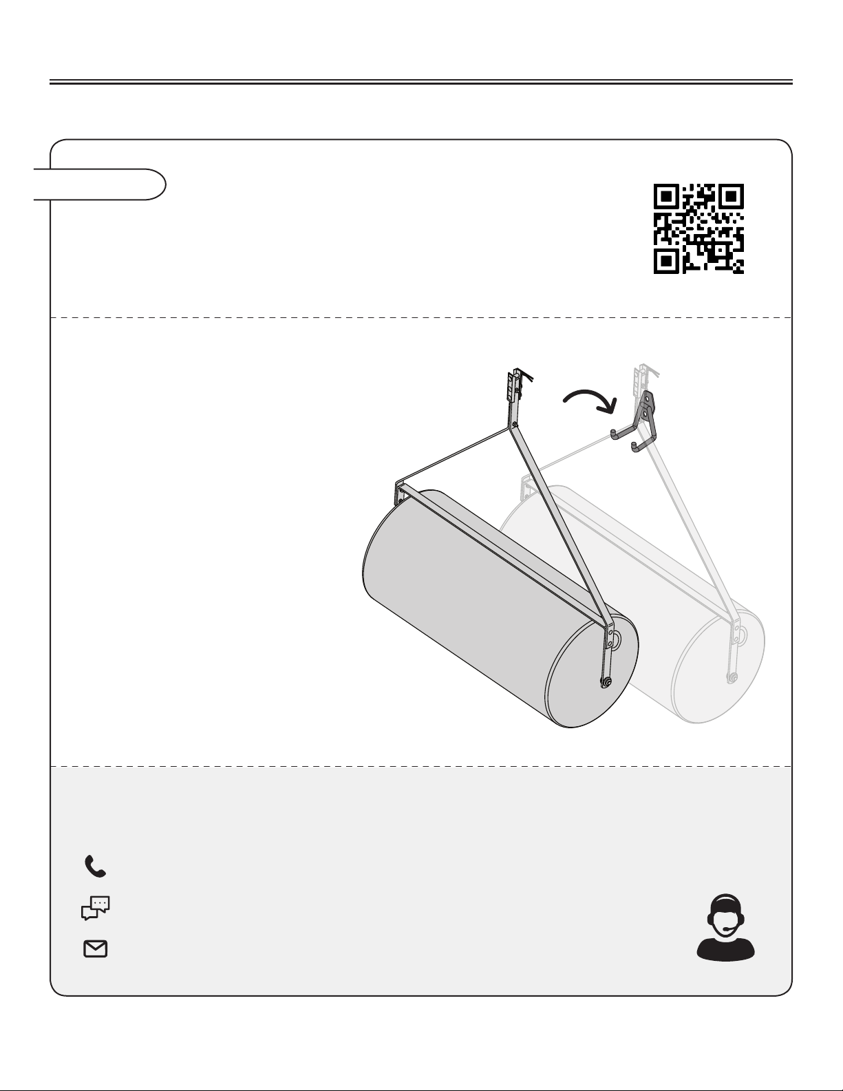
Assembly Tip
You can check out our step-by-step Lawn Roller assembly video
by visiting our Brinly YouTube page, Brinly.com, or by scanning
this QR code with your smartphone.
ASSEMBLY
WE RECOMMEND THE FOLLOWING STEPS
FOR THE CARE OF YOUR ROLLER TO PREVENT
FLAT SPOTS:
- For longest life, drain the roller
and leave the plug out.
If possible, hang the roller when not in
use to prevent the potential occurrence
of the drum developing a at spot.
- If a at spot develops during
storage, rst ensure the roller is empty.
Next, leave it out in the sun to warm
(we recommend sitting it out on
pavement for at least one day).
Once this is complete, roll it around
to reduce the at area.
If you have questions, are missing parts or need replacement parts, don’t go back to the store!
Please nd your product serial number and model number, then contact our Customer Service department:
In North America and Canada call Toll-Free: 877-728-8224
Chat online: www.brinly.com
Email: customerservice@brinly.com
7L-1681BH-M
English Manual
3
1
8
4
10
7
7
11
3
2
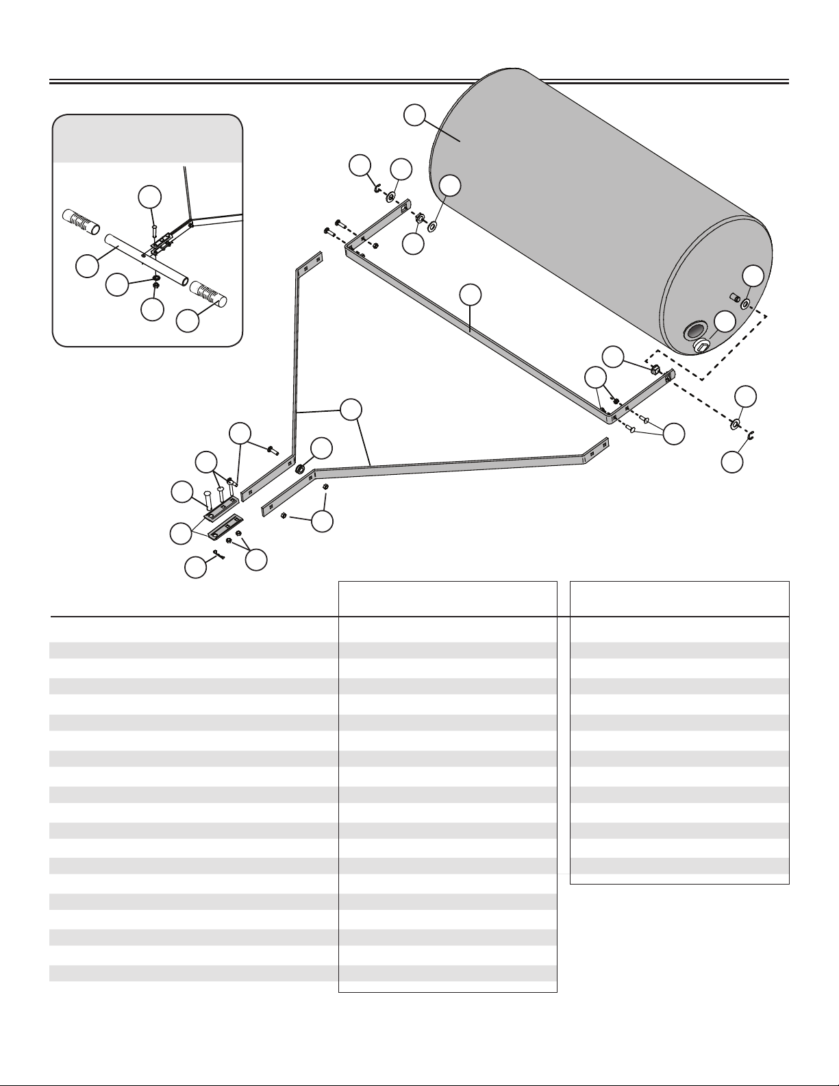
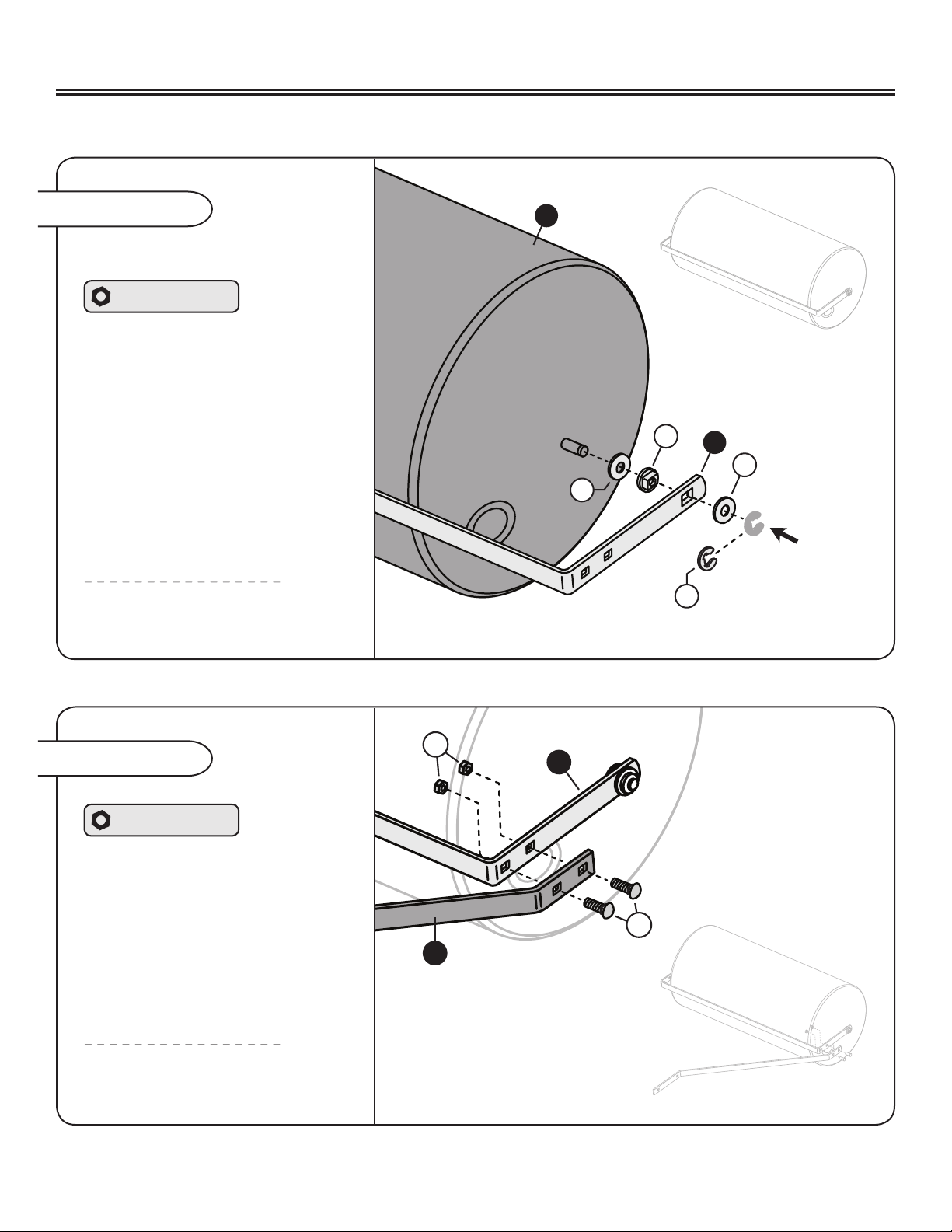
ASSEMBLY
Assembly Step 1
Attaching the Scraper Bar
Add a 5/8” at washer (7) to the
Roller Drum (2) as illustrated.
Slide a square bearing (10) into
the large square hole at the end of
the Scraper Bar (3) and add to the
Roller Drum.
Add another 5/8” at washer (7).
Secure everything in place by
sliding a 5/8” E-ring (11) into the
slot at the end of the roller drum (2).
Hardware Panel A
Repeat this step on the
other end of the drum.
Assembly Step 2
Repeat this step on the
other end of the drum.
Align the Frame Extension Bar (1)
as illustrated.
From the outside, run two
5/16 x 1” Carriage Bolts (4) through
the Extension Bar (1) and Scraper
Bar (3) as illustrated.
Secure everything in place with two
5/16” Nylon Lock Nuts (8).
Hardware Panel B
8L-1681BH-MEnglish Manual
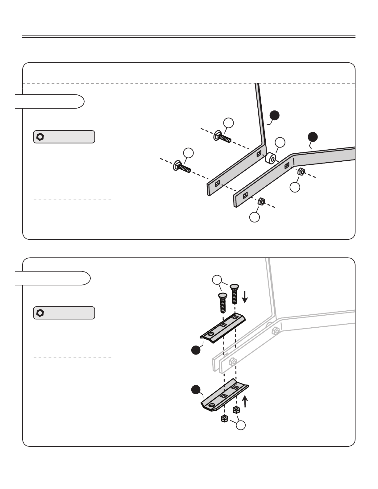
1
1
5
5
12
8
8
NOTE: Do not tighten the lock nuts added on this step completely (until Assembly Step 4-A is complete).
Assembly Step 3
Connecting the Frame Extension Bars
Center the Spacer (12) between the second
hole of the Extension Bars (1) and run a
5/16” Carriage Bolt (5) through.
Loosely add a 5/16” Lock Nut (8).
Hardware Panel C
Add the second 5/16” Carriage bolt to
the Extension Bars (1) and secure with
the additional 5/16” Lock Nut (8).
Assembly Step 4
Align the Clevis plates (20)
as illustrated.
NOTE: The two bolts that will be added on
this step need to straddle the Carriage Bolt
at the very end of the extension bars.
Run two 5/16 x 2-1/4” Carriage
Bolts (6) through the Clevis Plates (20).
Secure in place with two 5/16” Nylon
Lock Nuts (8).
Hardware Panel D
Attaching the Clevis
20
20
6
8
ASSEMBLY
9L-1681BH-M
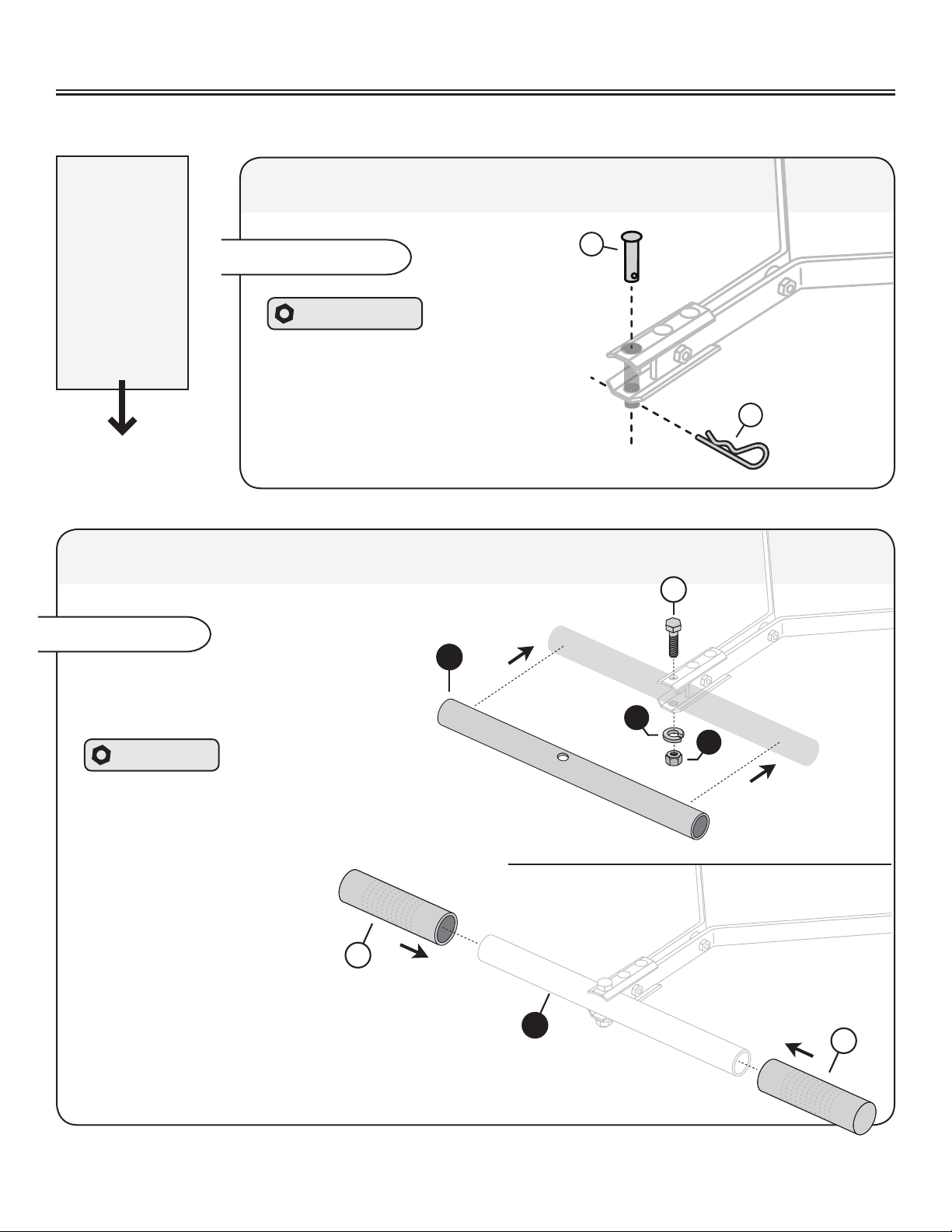
English Manual
15
16
18
17
Slide the Handle (15) between the Clevis
plates as illustrated. NOTE: Be sure to align
the openings of the clevis and handle.
Hardware Bag
Run a 1/2 x 2-1/4” Hex Bolt (16) through the Clevis
plates and handle. Secure with a 1/2” lock washer (18)
and a 1/2” lock nut (17).
Slide the grips (19)
over the ends of the
handle (15).
Assembly Step 6
If you are
assembling
PRC-241BH or
PRC-241BH-A:
Skip Step 5
and continue
to Assembly
Step 6
13
14
Assembly Step 5
Add the hitch pin (13) through remaining
openings of the Clevis (20) and secure
with a Hitch Pin Cotter (14).
Skip Step 6 and continue to Assembly Step 7.
Hardware Panel D
PRT-361 BH, PRT-361S BH & PRT-481S BH: Attaching the Clevis
PRC-241 BH: Attaching the Handle
15
19
19
ASSEMBLY
10 L-1681BH-MEnglish Manual
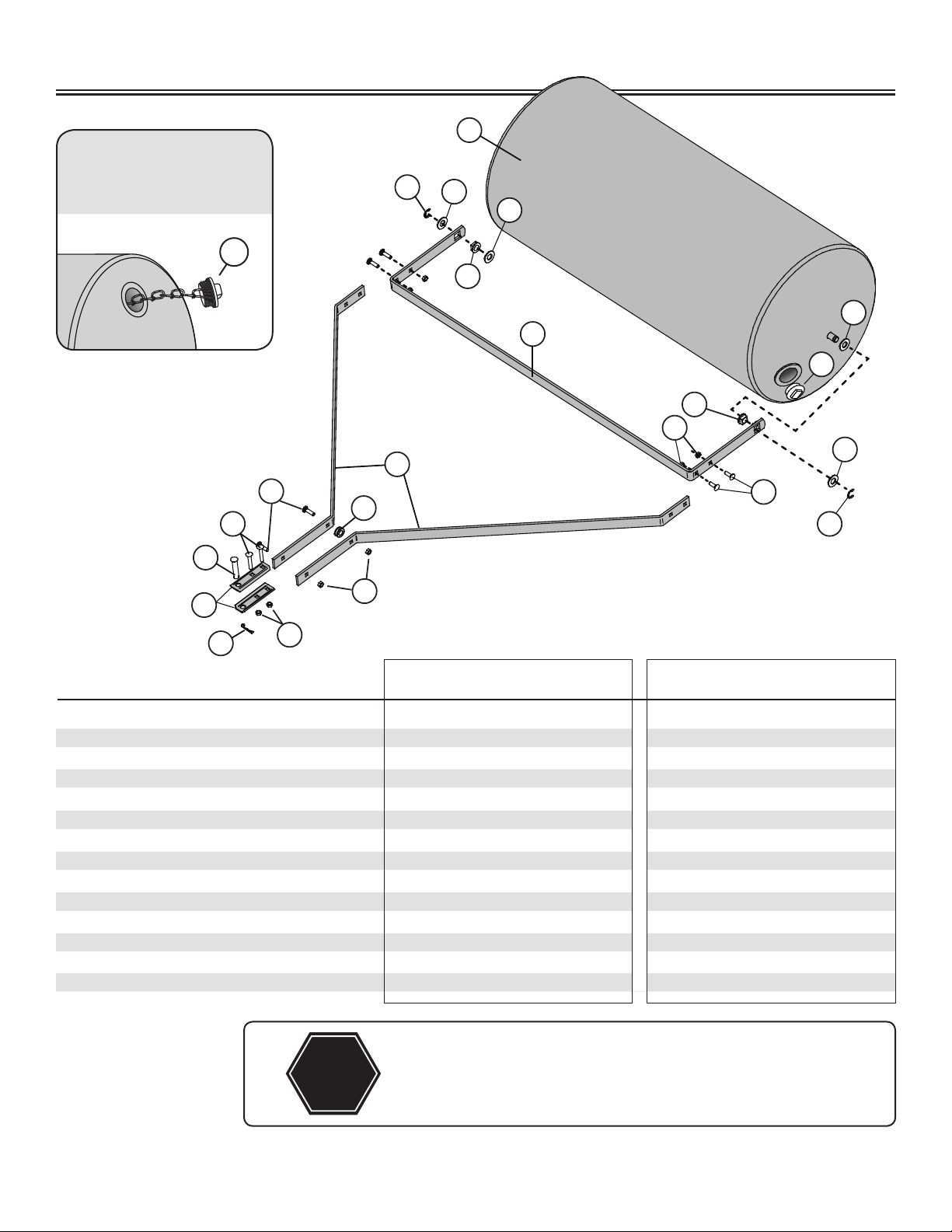
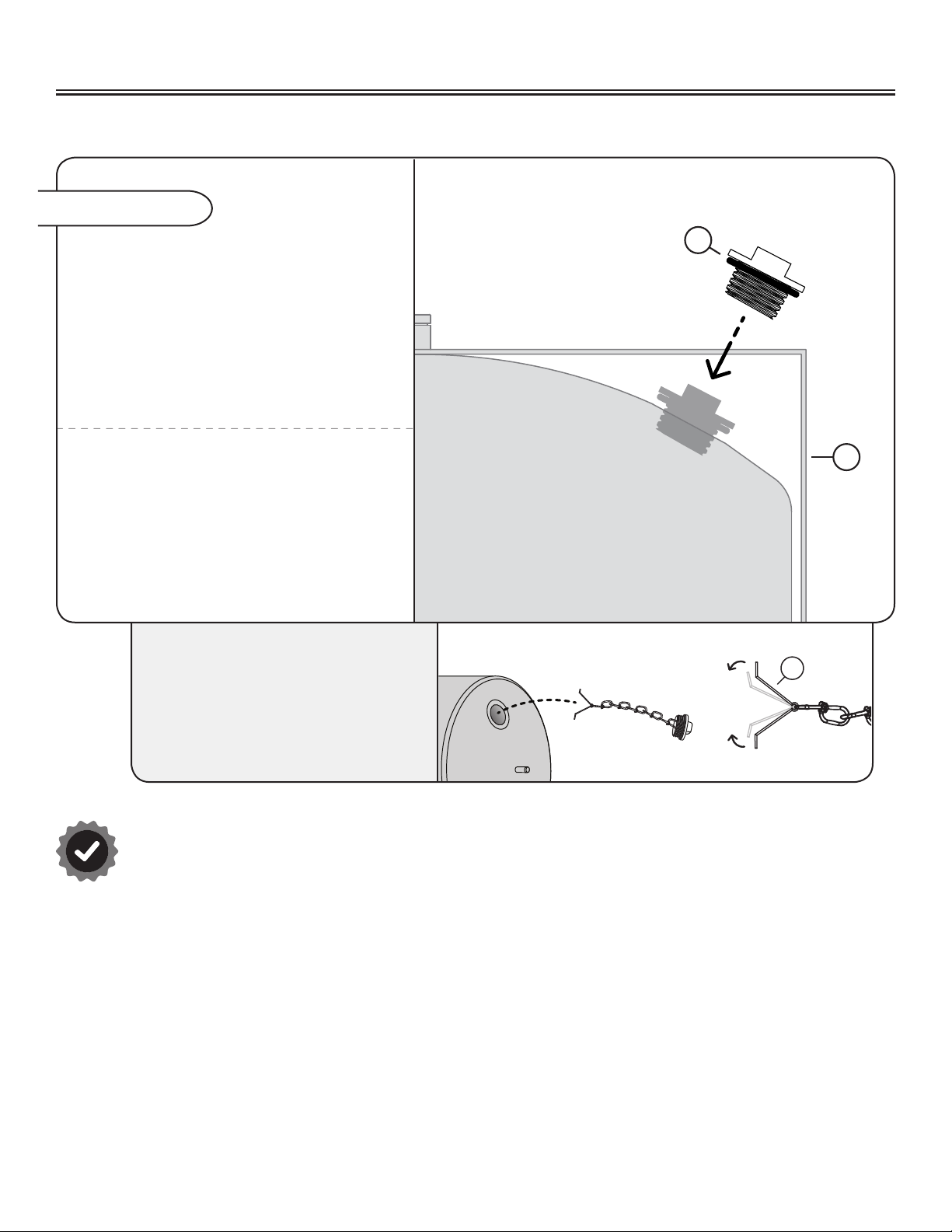
Assembly Step 7
Adding the Roller Plug
When installing the plug (9) please note the
plug has an o-ring, ensure o-ring properly
seats against the roller. A portion of the plug
will extend from the roller, however, it will not
interfere with the scraper bar (3).
Hand tighten as far as possible,
if the plug is leaking, ensure o-ring
is not bulging outside of the plug.
NOTE: A wrench around the plug handle
can be used to further tighten if necessary.
ADDITIONAL NOTE:
Some models come with a
tethered plug. This plug can be
attached by squeezing the tethered
spring. Next insert the plug into roller,
rotating the plug in place.
3
9
Assembly is complete.
9
ASSEMBLY
This manual suits for next models
7
Table of contents
Other Brinly Farm Equipment manuals


