
Bosch LTC 3384 User manual

Series DC-iris Zoom Lenses
Installation Manual
EN LTC 3384
Guide de l'utilisateur
FR LTC 3384
Bedienungsanleitung
DE LTC 3384
Manual de instrucciones
ES LTC 3384
Handleiding
NL LTC 3384
Manuale d'istruzioni
IT LTC 3384
LTC3384_IN_93583.qxd 6/26/03 2:35 PM Page 1

Important Sa ety Instructions
Applications
The Bosch 1/3” DC-iris Zoom
Lenses provide high quality optics
or state-o -the-art CCTV cameras.
DC-iris
The DC-iris direct drive eature
automatically adjusts the iris opening
according to lighting conditions. This
ensures optimum picture quality in
applications with changing light
levels, or example, in outdoor
observation.
Zoom and Focus
Zoom and ocus are driven by
motors, allowing sharp images
ranging rom wide angle to
telephoto.
Connection and Mounting
The lenses are itted with two
terminated cables and a CS camera
mount.
Type Number Zoom Mount
LTC 3384/21 10x, 6-60 mm CS
DC-iris Connection: A 200 mm
cable terminated with a 4-pin EIAJ
plug or direct connection to Bosch’
camera heads.
Zoom and Focus Connection: A
400 mm cable terminated with 8-pin
connector or connection to a zoom/
focus controller.
Lens Mounting: To attach the lens to
the camera head:
1. Screw the lens into the camera
head until it completely stops.
2. Rotate the lens back to the
desired position (there is a
riction coupling between the
CS-mounting and the lens body
that allows 360° rotation).
Controls
Zoom and Focus Control: Zoom
and ocus are controlled by speci ic
signals supplied rom the zoom/ ocus
controller via the zoom/ ocus control
cable. The zoom and ocus motors
are activated while the signals are
present and stop when the signals
are removed.
LTC 3384 | Installation Instruction EN | 2
Bosch Security Systems | 06 2003 | ersion 93584
Warning: Do not use the
lens to look at the sun. It
may cause loss o sight.
Attention: Do not direct
the lens into the sun. It
may cause a ire.
Caution: Use 1/3” format CS-
mount lenses only with 1/3”
format cameras with CS-mount.
LTC3384_IN_93583.qxd 6/26/03 2:35 PM Page 2

Zooming and Focusing procedure:
1. Apply zoom control signals to
set the zoom to “TELE” end.
2. Apply focus control signals and
align focus.
3. Apply the zoom control signals
to set the required angle of field.
4. If the image becomes out of
focus due to zooming, adjust the
back focus (see below).
Back Focus Adjustment:
4-wire control
3-wire control
(which can be focused on
easily).
2. Set the zoom to “WIDE” and
align the focus with the camera
(refer to the camera
instructions).
3. Set the zoom to “TELE” and
align the focus with the lens.
4. Repeat the above procedures
several times until the focus at
both ends of the zoom range
(WIDE and TELE) are most
appropriate.
Cable Connection
Focus/Zoom (8-Pin Female Connector)
Pin Polarity Direction
Focus 6 + Inf.
5 -
6 - Near
5 +
Pin Polarity Direction
Zoom 6 + Wide
4 -
6 - Tele
4 +
|4833CTL3|NE Installation Instruction
Bosch Security Systems | 06 2003 | Version 93584
LTC3384_IN_93583.qxd 6/26/03 2:35 PM Page 3
Pin Polarity Direction
Focus 2&6 + Inf.
5 -
2&6 - Near
5 +
Pin Polarity Direction
Zoom 2&6 + Wide
2&6: Connect pins 2 and 6 together
4 -
2&6 - Tele
4 +
Specifications
Focus/Zoom
Input Voltage: 6 - 12 VDC
Current Consumption: 70 mA max.
Motorization Speed: Approx. 3-4 s
DC-iris
Response speed: Approx. 2 s
Temperature
Range: -5 to +50 °C
(23 - 122 °F)
LTC 3384 | Installation Instruction EN | 4
Bosch Security Systems | 06 2003 | Version 93584
LTC3384_IN_93583.qxd 6/26/03 2:35 PM Page 4
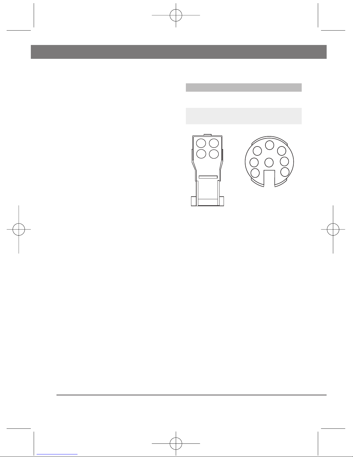
DC-iris (4-Pin DC-Iris Lens Connector)
Pin Polarity Connection
3 + Driving Coil
4 -
1 - Damping Coil
2 +
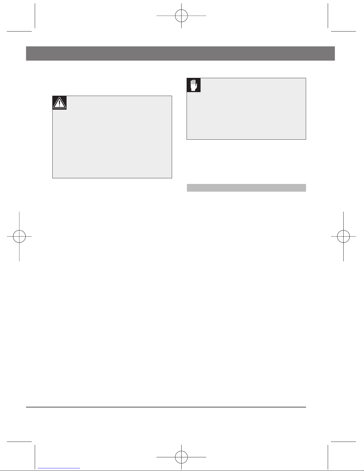
DC-Iris Connector 8-PIN Female Connector
(both viewed from solder side)
1
2
3
4
6
8
3
5
2
4
1
7
Sécurité
Applications
Les objecti s 1/3" iris-DC zoom à
diaphragme automatique Bosch sont
constitués d'éléments optiques de
haute qualité. Ils sont destinés aux
caméras de TV en circuit ermé les
plus per ormantes.
Diaphragme automatique
Le diaphragme automatique adapte
automatiquement l'ouverture de l'iris
aux conditions d'éclairement. II
garantit une qualité optimale de
l'image dans des applications sujettes
à des variations de niveaux de
lumière, par exemple dans les
applications en extérieur.
Zoom et mise au point
Le réglage de zoom et de mise au
point sont contrôlés par des moteurs,
ce qui permet d'obtenir des images
très nettes soit en objecti grand-
angle soit en téleobjecti .
Raccordements et ixation
Ces objecti s zoom sont munis de
deux câbles avec iche et d'une
monture CS.
Numéro de typer Zoom Fixation
LTC 3384/21 10x, 6-60 mm CS
Raccordement du diaphragme
automatique: Les objecti s sont
dotés d'un câble de 20 cm de long
terminé par une prise à 4 broches
pour le raccordement direct sur les
caméras Bosch.
Connecteur pour zoom et mise au
point: Ils sont également équipés
d'un câble de 40 cm de long terminé
par un connecteur 8 broches pour le
raccordement direct sur un récepteur
de télécommande de zoom/mise au
point.
Montage de 'objecti : Pour ixer
l'objecti sur la caméra:
1. Visser à ond l'objecti sur la
caméra jusqu' à in.
FR | 5 LTC 3384 | Guide de l'utilisateur
Bosch Security Systems | 06 2003 | ersion 93584
Attention: N'utilisez pas
l'objecti pour regarder le
soleil. Ceci pourrait
occasionner une cécité.
Attention: Ne dirigez pas
l'objecti vers le soleil.
Ceci pourrait occasionner
un incendie.
Attention: Avec les caméras à
capteur 1/3" et monture CS, il
est recommandé d'utiliser
uniquement des objectifs à
monture CS de format 1/3" ou
1/2"
LTC3384_IN_93583.qxd 6/26/03 2:35 PM Page 5

2. Faire pivoter l'arrière de
l'objecti jusqu' à la position
désirée (il existe un couple de
riction entre la monture CS et
le corps de l'objecti , permettant
une rotation sur 360°).
Commandes
Commandes de zoom et de mise
au point: Le zoom et la mise au
point sont commandés par des
signaux émis à partir du contrôleur
de télécommande de zoom/mise au
point, par l'intermédiaire du câble de
commande zoom/mise au point. Les
moteurs du zoom et de mise au point
se déclenchent dès réception des
signaux. Ils s'arrêtent guard les
signaux sont supprimés.
Procédure d'exploitation du zoom
et de Ia mise au point:
1. Appliquer les signaux de
commande du zoom de manière
à régler le zoom du côté
"TELE".
2. Appliquer les signaux de la
commande de mise au point
pour régler celle-ci.
3. Appliquer les signaux de
commande de zoom a in de
régler l'objecti pour obtenir
l'angle de champ requis.
4. Si, en réglant le zoom, l'image
perd sa netteté, régler le tirage
optique (voir ci-dessous).
Réglage du tirage optique:
1. Sélectionner un objet
relativement grand (sur lequel il
sera acile de aire la mise au
point) et éloigné de 15 mètres
minimum.
2. Régler le zoom sur "WIDE"
(Grand angle) et aligner la mise
au point avec la monture de la
caméra (se reporter à la notice
de la caméra, réglage du tirage
optique).
3. Régler le zoom sur "TELE" et
régler la mise au point sur la
bague de l'objecti .
4. Recommencer à plusieurs
reprises les procédures ci-dessus
jusqu'à ce que la mise au point
soit constante sur toute la
gamme de réglage du zoom
(GRAND-ANGLE et
TELEOBJECTIF).
LTC 3384 | Guide de l'utilisateur FR | 6
Bosch Security Systems | 06 2003 | ersion 93584
LTC3384_IN_93583.qxd 6/26/03 2:35 PM Page 6
Branchement du câble
Mise au point/Zoom (Connecteur 8-
Broche)
Broche Polarité Direction
Mise au 2 + Inf.
point 5 -
2 - Près.
5 +
Broche Polarité Direction
Zoom 6 + Grand angle
4 -
6 - Téléobjectif
4 +
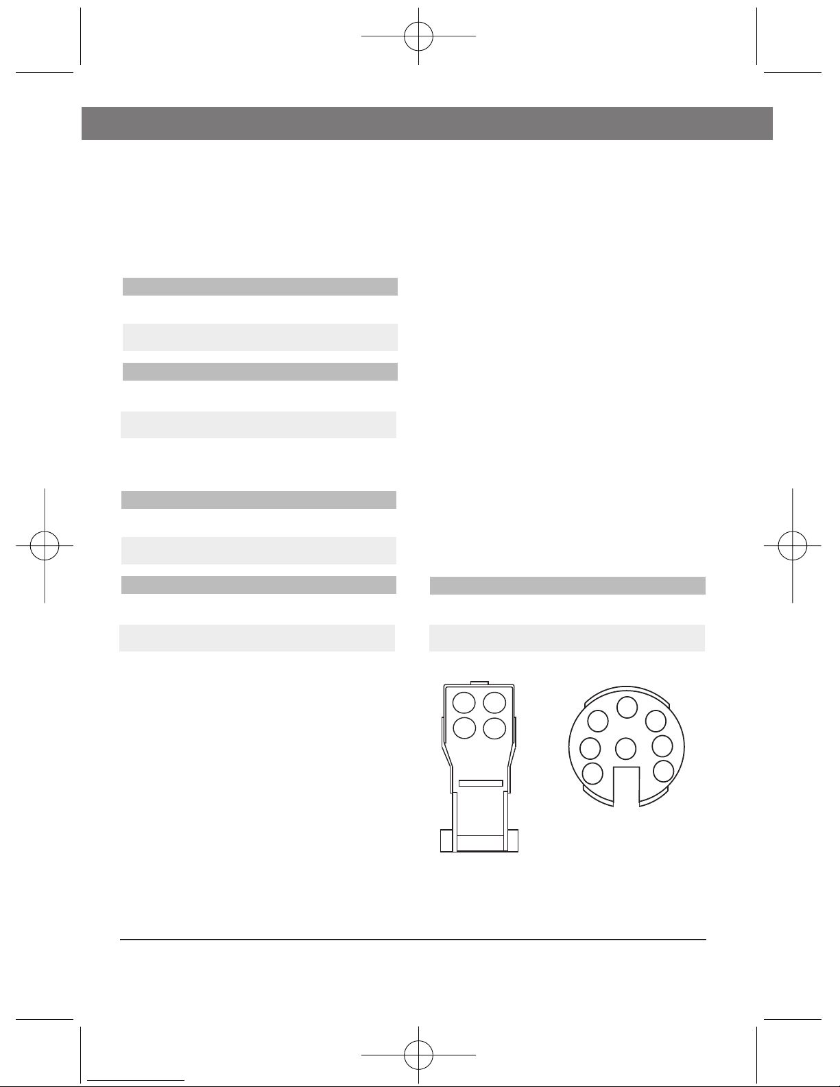
Iris DC (Connecteur 4-Broche)
Broche Polarité Connexion
3 + Bobine d'entraînement
4 -
1 - Bobine d'amortissement
2 +
Connecteur iris DC Connecteur 8-Broche
(Vue depuis le côté des soudures)
Spécifications
Mise au point/Zoom
Tension en
Commande 4 fils
Commande 3 fils
entrée : 6 - 12 V cc
Consommation
réelle : 70 mA max.
Vitesse de
motorisation : Approx. 3-4 sec.
Iris DC
Vitesse de
réaction : Approx. 2 sec.
Température
Plage : -5 à +50°C
|4833CTL7|RF Guide de l'utilisateur
Bosch Security Systems | 06 2003 | Version 93584
1
2
3
4
6
8
3
5
2
4
1
7
LTC3384_IN_93583.qxd 6/26/03 2:35 PM Page 7
Broche Polarité Direction
Mise au 2&6 + Inf.
point 5 -
2&6 - Près.
5 +
Broche Polarité Direction
Zoom 2&6 + Grand angle
4 -
2&6 - Téléobjectif
4 +
2&6: reliez les broches 2 et 6
Sicherheit
Anwendung
Die Bosch 1/3” Zoom-Objektive mit
gleichstromgesteuerter Blende
optischen Qualität sind ür den
Einsatz an modernen
Überwachungskameras bestimmt.
Blendenautomatik
Die Blendenautomatik paßt die
Blendenö nung den gegebenen
Lichtverhältnissen an. Die Automatik
sorgt ür eine optimale Bildqualität
auch bei stark schwankenden
Beleuchtungsverhältnissen, z. B. Im
Freien.
Zoom und Fokus
Die Einstellungen ür Zoom und
Fokus er olgen mit Hil e von
Motoren. Dies gewährleistet eine
hohe Bildschär e vom Weitwinkel-
bis Tele-Bereich.
Anschlüsse und Installation
Die Objektive werden an der
Kamera mechanisch über den CS-
Mount und elektrisch über zwei
Kabel mit Steckverbindern
angeschlossen.
Typennummer Zoom Objektiv-Fassung
LTC 3384/21 10x, 6-60 mm CS
Anschluß der Blendenautomatik:
An den Objektiven be indet sich ein
200 mm langes Kabel mit einem 4-
poligen EIAJ-Stecker zum direkten
Anschluß an Bosch
Uberwachungskameras.
Anschluß ur Zoom und Fokus: Ein
weiteres 400 mm langes Kabel mit
8 poligem Stecker ür Zoom
und Fokus angeschlossen.
Einsetzen des Objektivs: Das
Objektiv wird wie olgt an der
Kamera be estigt:
1. Schrauben Sie das Objektiv bis
zum Anschlag in die Kamera.
2. Drehen Sie das Objektiv in die
gewünschte Position (zwischen
dem CS-Mount und dem
Objektivgehäuse be inder sich
eine Rutschkupplung, die eine
Drehung um 360° erlaubt).
LTC 3384 | Bedienungsanleitung DE | 8
Bosch Security Systems | 06 2003 | ersion 93584
Warnung: Mit diesem
Objektiv nicht in die
Sonne blicken. Erblindung
kann die Folge sein.
Achtung: Das Objektiv
nicht in die Sonne richten.
Brandge ahr
Achtung: CS-Mount Objektive
für das 1/3” Format dürfen nur
an 1/3” Kameras mit CS-Mount
eingesetzt werden.
LTC3384_IN_93583.qxd 6/26/03 2:35 PM Page 8

Steuerung
Steuerung von Zoom und Fokus:
Zoom und Fokus werden durch
eigene Steuersignale vom
Zoom/Fokus-Steuergerät über das
entsprechende Kabel eingestellt. Die
Einstellmotoren für Zoom und Fokus
drehen, solange das Signal anliegt,
und halten an, sobald das
entsprechende Steuersignal wieder
abgeschaltet wird.
Einstellen des Zooms und der
Fokussierung:
1. Bringen Sie das Zoom mit Hilfe
des entsprechenden Steuergeräts
an die Tele-Endposition.
2 Stellen Sie mit Hilfe des Fokus-
Steuersignals die Bildschärfe ein.
3 Stellen Sie nun mit dem Zoom-
Steuersignal den gewünschten
Bildwinkel ein.
4 Wenn sich beim Verstellen des
Zooms die Bildschärfe ändert,
muß das Auflagemaß justiert
werden (siehe unten).
Einstellung des Auflagemaßes:
1. Richten Sie die Kamera auf
einen größeren Gegenstand (der
sich leicht scharfstellen (läßt).
2 Bringen Sie das Zoommobjektiv
in Stellung Weitwinkel und
3-Draht steuerung
4-Draht steuerung
2&6: Pin 2 und 6 gemeinsam verbinden
stellen Sie die Schärfe über das
Auflagemaß der Kamera em
(siehe Bedienungsanleitung der
Kamera).
3 Stellen Sie das Zoom auf Tele
und stellen Sie am Objektiv
scharf.
4 Wiederholen Sie diesen Vorgang
solange, bis sich bei den beiden
Fokuseinstellungen (Weitwinkel
und Tele) keine Verbesserung
mehr ergibt.
Kabelanschluß
Fokus/Zoom (Anschluß 8-Stift)
Stift Polarität Richtung
Fokus 2 + Unendlich
5 -
2 - Nah
5 +
Stift Polarität Richtung
Zoom 6 + Weitwinkel
4 -
6 - Tele
4 +
|4833CTL9|ED Bedienungsanleitung
Bosch Security Systems | 06 2003 | Version 93584
LTC3384_IN_93583.qxd 6/26/03 2:35 PM Page 9
Stift Polarität Richtung
Fokus 2&6 + Unendlich
5 -
2&6 - Nah
5 +
Stift Polarität Richtung
Zoom 2&6 + Weitwinkel
4 -
2&6 - Tele
4 +

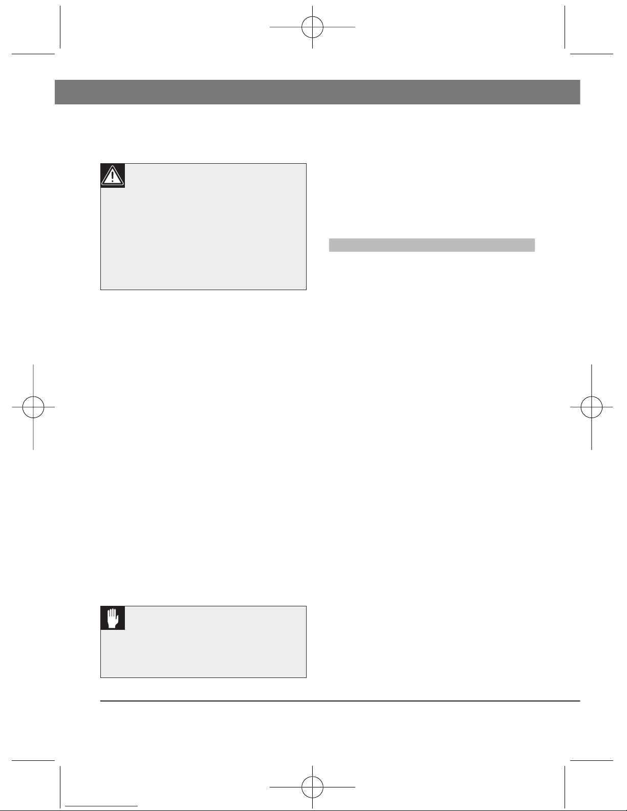
Anschluß für Anschluß 8-Stift
gleichstromgesteuerte
Blendenregelung
(Von der Löseite aus bettrachtet)
Technische Daten
Fokus/Zoom
Eingangsspannung: 6 - 12 VDC
Stromverbrauch: max. 70 mA
Motorgeschwindigkeit: ca. 3 - 4 Sek.
Gleichstromgesteuerte
Blendenregelung
Reaktionsgeschwin-
digkeit: ca. 2 Sek.
Temperatur
Temperatur-bereich: -5 bis +50°C
LTC 3384 | Bedienungsanleitung DE | 10
Bosch Security Systems | 06 2003 | Version 93584
1
2
3
4
6
8
3
5
2
4
1
7
LTC3384_IN_93583.qxd 6/26/03 2:35 PM Page 10
Gleichstromgesteuerte Blende
(Anschluß 4-Stift)
Pin Polarität Anschluß
3 + Antriebsspule
4 -
1 - Dämpferspule
2 +
Table of contents
Languages:
Other Bosch Camera Lens manuals

Popular Camera Lens manuals by other brands


Sony
Sony VCL-ST30 operating instructions

Canon
Canon FD 35 - 70 mm instructions

Sony
Sony SAL-85F14Z - 85mm f1.4 Carl Zeiss Planar T Coated Telephoto... operating instructions

ARRI
ARRI Lenses brochure

Panasonic
Panasonic LUMIX G X Vario 45-175mm f/4.0-5.6 operating instructions

Nikon
Nikon AF-S VR 24-120 f/3.5-5.6G IF-ED instruction manual


