Blaupunkt BPT-V03-12 User manual

Czerp korzyści!
Hymon Fotowoltaika Sp z o.o.
ul. Dojazd 16A 33-100 Tarnów
Wyłączny dystrybutor nowoczesnych systemów
GRID-TIED PV STRING INVERTER
USER MANUAL
BPT-V03-15
BPT-V03-12
7.6 HOW TO BROWSE THE LOAD POWER OF YOUR PV GRID-TIEPLANT ON MONITORING PLATFORM?
Hymon Fotowoltaika Sp z o.o.
ul. Dojazd 16A 33-100 Tarnów
Wyłączny dystrybutor nowoczesnych systemów
www.hymon.pl
2
USER MANUAL
1. INTRODUCTION
1.1 APPEARANCE INTRODUCTION
1.2 PARTS LIST
2. SAFETY WARNINGS AND INSTRUCTIONS
2.1 SAFETY SIGNS
2.2 SAFETY INSTRUCTIONS
2.3 NOTES FOR USING
3. OPERATION INTERFACE
3.1 INTERFACE VIEW
3.2 STATUS INDICATOR
3.3 BUTTONS
3.4 LCD DISPLAY
4. PRODUCT INSTALLATION
4.1 SELECT INSTALLATION LOCATION
4.2 INVERTER INSTALLATION
5. ELECTRICAL CONNECTION
5.1 DC INPUT TERMINAL CONNECTION
5.2 AC INPUT TERMINAL CONNECTION
5.3 THE CONNECTION OF THE GROUND LINE
5.4 MAX. OVER CURRENT PROTECTION DEVICE
5.5 INVERTER MONITORING CONNECTION
5.7 CONFIGURATION OF DATALOGGER
6. STARTUP AND SHUTDOWN
6.1 START UP THE INVERTER
6.2 INVERTER SHUTDOWN
5.6 INSTALLATION OF DATALOGGER
7. ZERO EXPORT FUNCTION VIA SUN LIMITER
7.1 SUN LIMITER FUNCTION WIRING DIAGRAM
7.2 CONNECT THE SUN LIMITER TO INVERTER
7.3 USE OF ZERO EXPORT FUNCTION
8. GENERAL OPERATION
8.1 THE INITIAL INTERFACE
8.2 SUBMENUS IN THE MAIN MENU
8.3 SYSTEM PARAM SETTING
8.4 RUNNING PARAM SET
9. REPAIR AND MAINTENANCE
10. ERROR INFORMATION AND PROCESSING
10.1 ERROR CODE
11. SPECIFICATION
8.6 COMM. PARAM SET
8.5 PROTECT PARAM
7.5 NOTES WHILE USING ZERO EXPORT FUNCTION
7.4 ZERO-EXPORT FUNCTION (OPTION)

Hymon Fotowoltaika Sp z o.o.
ul. Dojazd 16A 33-100 Tarnów
Wyłączny dystrybutor nowoczesnych systemów
www.hymon.pl
3
1.1 APPEARANCE INTRODUCTION
1. INTRODUCTION
ABOUT THIS MANUAL
HOW TO USE THIS MANUAL
PHOTOVOLTAIC GRID-CONNECTED SYSTEM
Application of inverter in photovoltaic power system
Inverter Metering
PV array Power grid
Family load
Pic 1.1 Front view Pic 1.2 Bottom view
ACDC Normal Alarm
ESC UP Down Enter
DC SWITCH
RS485
RS232/485
limiter
ON
OF F
Read the manual and other related documents before performing any operation on the inverter. Documents must be stored
carefully and be available at all times. Contents may be periodically updated or revised due to product development.
The information in this manual is subject to change without notice.
On-grid inverter can convert solar panel DC power into AC power which can directly input to the grid. Its appearance is
shown below. These models contain BPT-V03-12、BPT-V03-15. The following is collectively referred to as ‘inverter’.
The manual mainly describes the product information, guidelines for installation, operation and maintenance. The manual
cannot include complete information about the photovoltaic (PV) system.
Hymon Fotowoltaika Sp z o.o.
ul. Dojazd 16A 33-100 Tarnów
Wyłączny dystrybutor nowoczesnych systemów
www.hymon.pl
4
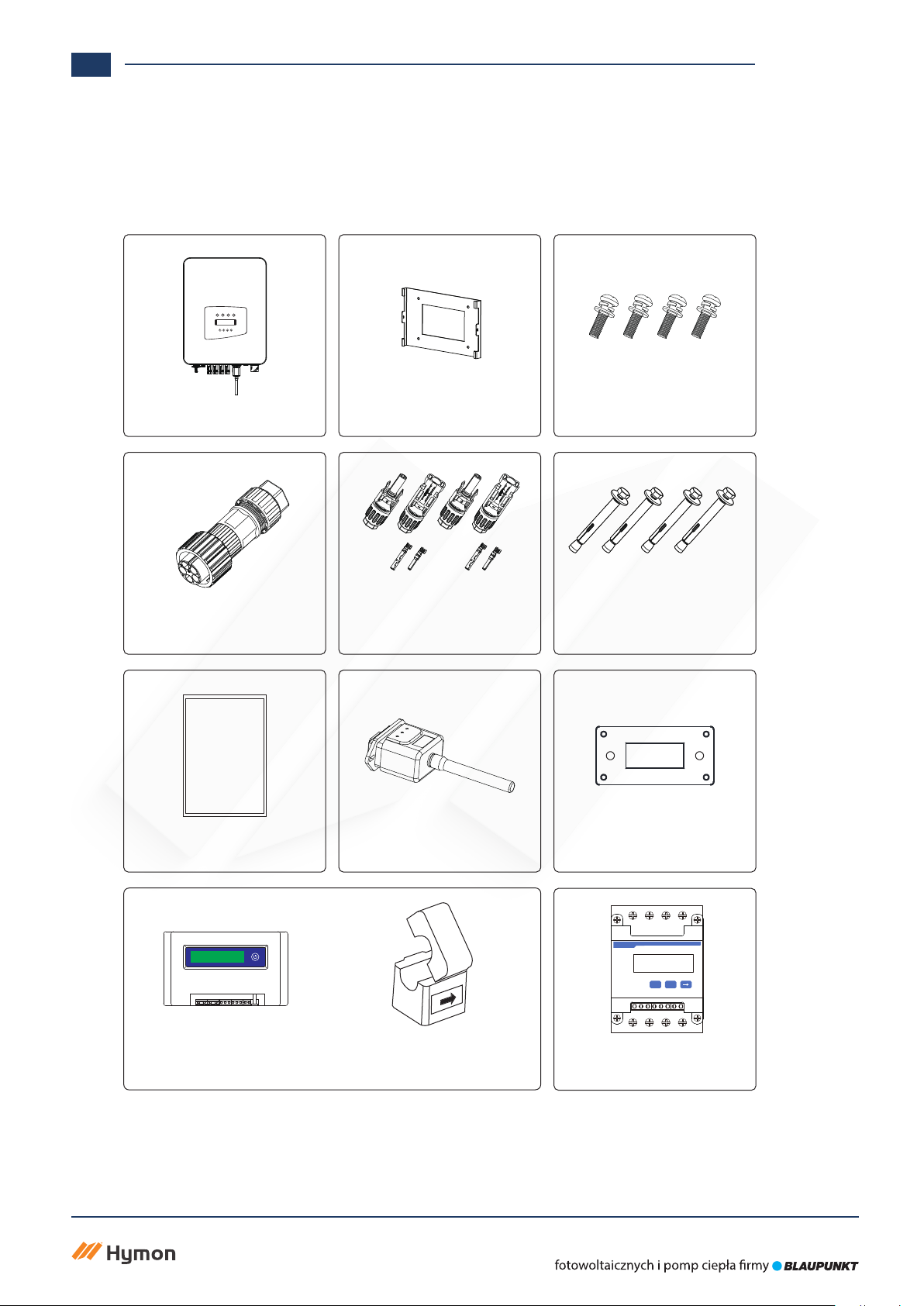
1.2 PARTS LIST
Please check the following table, to see whether all the parts are included in the package:
Wall mounting bracket x1
Mounting stainless steel
screws M4×12
x4
Grid-tied PV String Inverter
x1
DC power connectors
(including Inserted spring)
x3
Stainless steel anti-collision
bolt M6×80
x4
AC power connectors x1
User
manual
User manual x1
Square hole sealing plate
(For WIFI function)
x1
Datalogger (optional) x1
Meter(optional)
x 1
Three-Phase Smart Meter
SET ESC
SUN limiter(optional) x 1
When ordering the sun limiter, it will includes 3pcs CT.
*Sensor Clamp x 3
- 19 - - 20 -
ACDC Normal Alarm
ESC UP Down Enter

Hymon Fotowoltaika Sp z o.o.
ul. Dojazd 16A 33-100 Tarnów
Wyłączny dystrybutor nowoczesnych systemów
www.hymon.pl
5
2. SAFETY WARNINGS AND INSTRUCTIONS
2.1 SAFETY SIGNS
2.2 SAFETY INSTRUCTIONS
Improper use may result in potential electric shock hazards or burns. This manual contains important instructions that
should be followed during installation and maintenance. Please read these instructions carefully before use and keep them
for future reference.
Safety symbols used in this manual, which highlight potential safety risks and important safety information,are listed
as follows:
Shock Hazard:
Caution, risk of electric shock symbol indicates important safety instructions,
which if not correctly followed, could result in electric shock.
High Temperature Hazard:
Caution, hot surface symbol indicates safety instructions, which if not correctly
followed, could result in burns.
Safety Hint:
Note symbol indicates important safety instructions, which if not correctly
followed, could result in some damage or the destruction of the inverter.
Warning:
Warning symbol indicates important safety instructions, which if not correctly
followed, could result in serious injury or death.
Shock Hazard:
Prohibit disassembling inverter case, there existing shock hazard, which may
cause serious injury or death, please ask qualied person to repair.
Warning:
Electrical installation of the inverter must conform to the safety operation rules
of the country or local area.
Warning:
Inverter adopts non-isolated topology structure, hence must insure DC input and
AC output are electrical isolated before operating the inverter.
Strictly prohibit grounding the positive and negative poles of the PV string.
Otherwise it will damage the inverter.
Shock Hazard:
When PV module is exposed to sunlight, the output will generate DC voltage.
Prohibit touching to avoid shock hazard.
Shock Hazard:
While disconnect the input and output of the inverter for maintenance, please
waits for at least 5 mins until the inverter discharge the remnant electricity.
High Temperature Hazard:
Local temperature of inverter may exceed 80℃while under operating.
Please do not touch the inverter case.
Hymon Fotowoltaika Sp z o.o.
ul. Dojazd 16A 33-100 Tarnów
Wyłączny dystrybutor nowoczesnych systemów
www.hymon.pl
6
2.3 NOTES FOR USING
The three phase string power inverter is designed and tested under related safety regulations. It can ensure the personal
safety of the user. But as a electric device, it may cause shock or injury by incorrect operation. Please operate the unit under
below requirements:
1. Inverter should be installed and maintained by qualied person under local standard
regulations.
2. Must disconnect the AC side rst, then disconnect DC side while doing installation and
maintenance, after that, please wait at least 5 mins to avoid getting shocked.
3. Local temperature of the inverter may exceed 80 ȭwhile under operating. Do not touch
to avoid getting injured.
4. All electrical installation must be in accord with local electrical standards, and after
obtaining the permission of the local power supply department, the professionals can
connect the inverter to the grid.
5. Please take appropriate anti-static measure.
6. Please install where children can not touch.
7. When starting the inverters, rst close the circuit breaker at the grid side, then close the
DC side; when closing the inverters, rst disconnect the circuit breaker at the AC side, then
disconnect the DC side.
8. Don’t insert or remove AC and DC terminals when the inverter is in normal operation.
9. The DC input voltage of the inverter must not exceed the maximum value of the model.
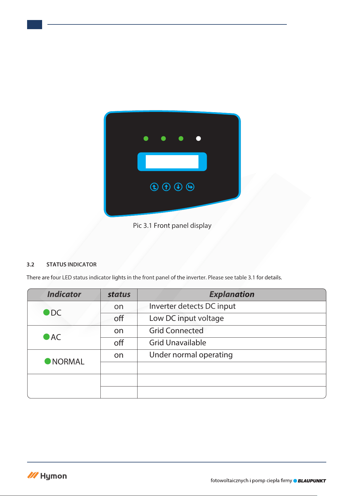
3.2 STATUS INDICATOR
3. OPERATION INTERFACE
Pic 3.1 Front panel display
3.1 INTERFACE VIEW
Table 3.1 Status indicator lights
There are four LED status indicator lights in the front panel of the inverter. Please see table 3.1 for details.
Explanation
Inverter detects DC input
Low DC input voltage
Grid Connected
Grid Unavailable
Under normal operating
Stop operating
Detected faults or report faults
Under normal operating
Indicator status
●DC
●AC
●NORMAL
●ALARM
on
o
on
o
on
o
on
o
Hymon Fotowoltaika Sp z o.o.
ul. Dojazd 16A 33-100 Tarnów
Wyłączny dystrybutor nowoczesnych systemów
www.hymon.pl
7
ACDC Normal Alarm
ESC UP Down Enter
3.3 BUTTONS
3.4 LCD DISPLAY
There are four keys in the front panel of the Inverter(from left to right): Esc, Up, Down and Enter keys.
The keypad is used for:
භScrolling through the displayed options (the Up and Down keys);
භAccess to modify the adjustable settings (the Esc and Enter keys).
The two-line Liquid Crystal Display (LCD) is located on the front panel of the Inverter, which shows the following
information:
භInverter operation status and data;
භService messages for operator;
භAlarm messages and fault indications.
Esc Up Down Enter
Hymon Fotowoltaika Sp z o.o.
ul. Dojazd 16A 33-100 Tarnów
Wyłączny dystrybutor nowoczesnych systemów
www.hymon.pl
8
Hymon Fotowoltaika Sp z o.o.
ul. Dojazd 16A 33-100 Tarnów
Wyłączny dystrybutor nowoczesnych systemów
www.hymon.pl
9
4.1 SELECT INSTALLATION LOCATION
4. PRODUCT INSTALLATION
To select a location for the inverter, the following criteria should be considered:
WARNING: Risk of re
භDo not install the inverter in areas containing highly ammable materials or gases.
භDo not install the inverter in potentially explosive atmospheres.
භDo not install in small closed spaces where air can not circulate freely. To avoid overheating,
always make sure the ow of air around the inverter is not blocked.
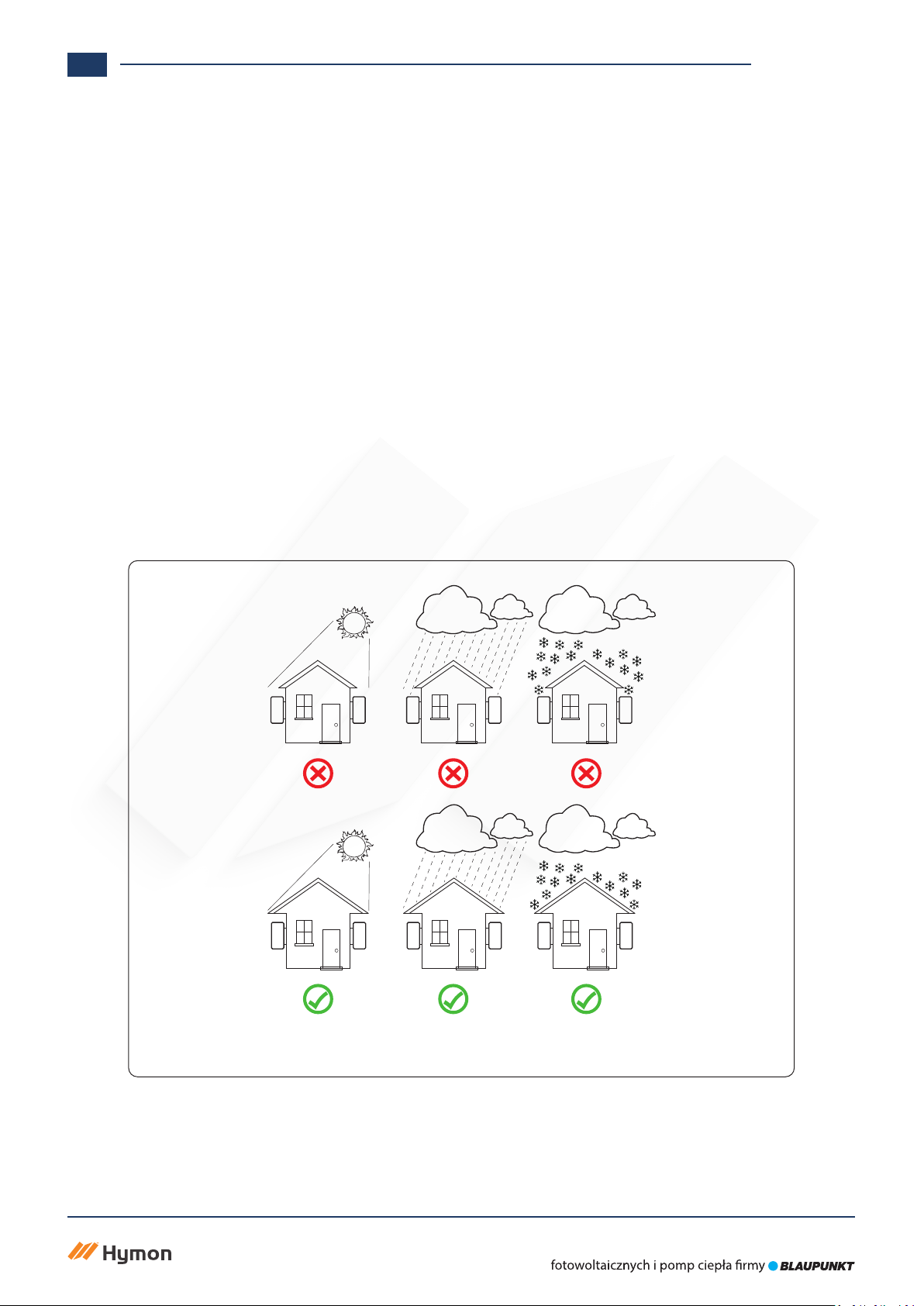
භExposure to direct sunlight will increase the operational temperature of the inverter and
may cause output power limiting. It is recommended that inverter installed to avoid direct
sunlight or raining.
භTo avoid overheating ambient air temperature must be considered when choosing the
inverter installation location. It is recommended that using a sun shade minimizing direct
sunlight when the ambient air temperature around the unit exceeds 100°F/40℃.
Pic 4.1 Recommended installation place

Hymon Fotowoltaika Sp z o.o.
ul. Dojazd 16A 33-100 Tarnów
Wyłączny dystrybutor nowoczesnych systemów
www.hymon.pl
10
භInstall on a wall or strong structure capable of bearing the weight.
භInstall vertically with a maximum incline of +/-15°. If the mounted inverter is tilted to an angle greater than the
maximum noted, heat dissipation can be inhibited, and may result in less than expected output power.
භ If install more than one inverter, must leave at least 500mm gap between each inverter. And each inverter must be at
least 500mm above and below.And must install the inverter at the place where children cannot touch. Please see picture
4.3.
භConsider whether the installation environment is helpful to see the inverter LCD display and indicator status clearly.
භMust oer a ventilate environment if inverter installed in the airtight house.
Safety Hint:
Do not place or store any items next to the inverter.
Pic 4.2 Installation Angle
≤15°
This manual suits for next models
1
Table of contents


