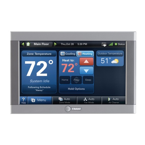
BLAUBERG Ventilatoren S25 User manual

SenSor control panel
EN
S25
USER’S MANUAL

Safety requirements..................................................................................................................................................................... 2
Purpose................................................................................................................................................................................................ 4
Technical data.................................................................................................................................................................................. 4
Installation, connection to power mains and set-up.............................................................................................. 5
Network setup................................................................................................................................................................................. 8
Control ................................................................................................................................................................................................. 9
Alarm and warning codes........................................................................................................................................................ 18
SAFETY REQUIREMENTS
CONTENTS
This user’s manual is a main operating document intended for technical, maintenance, and operating staff.
The manual contains information about the purpose, technical details, operating principle, design, and installation of the S25 unit (-s) and
all of its (their) modifications.
Technical and maintenance staff must have theoretical and practical training in the field of ventilation systems and should be able to
work in accordance with workplace safety rules as well as construction norms and standards applicable in the territory of the country.
The information in this user’s manual is correct at the time of the document’s preparation.
The Company reserves the right to modify the technical characteristics, design, or configuration of its products at any time in order to
incorporate the latest technological developments.
No part of this publication may be reproduced, stored in a retrieval system, or transmitted, in any form or by any means in any information
search system or translated into any language in any form without the prior written permission of the Company.
• Please read the user’s manual carefully prior to installing and operating the unit.
• All user’s manual requirements as well as the provisions of all the applicable local and national construction, electrical, and technical
norms and standards must be observed when installing and operating the unit.
• The warnings contained in the user’s manual must be considered most seriously since they contain vital personal safety information.
• Failure to follow the rules and safety precautions noted in this user’s manual may result in an injury or unit damage.
• After a careful reading of the manual, keep it for the entire service life of the unit.
• While transferring the unit control, the user’s manual must be turned over to the receiving operator.
www.blaubergventilatoren.de S25
2

UNIT MOUNTING AND OPERATION SAFETY PRECAUTIONS
• Disconnect the unit from power mains prior
to any installation operations.
• Do not operate the unit outside the
temperature range stated in the user's
manual.
• Do not operate the unit in aggressive or
explosive environments.
• Do not lay the power cable of the unit in
close proximity to heating equipment.
• While installing the unit follow the safety
regulations specific to the use of electric
tools.
• Do not change the power cable length at
your own discretion.
• Do not bend the power cable.
• Avoid damaging the power cable.
• Do not put any foreign objects on the power
cable.
• Unpack the unit with care.
• Do not use damaged equipment or cables
when connecting the unit to power mains.
• When the unit generates unusual sounds,
odour or emits smoke disconnect it from
power supply and contact the Seller.
• Do not touch the unit controls with wet
hands.
• Do not carry out the installation and
maintenance operations with wet hands.
• Do not wash the unit with water.
• Protect the electric parts of the unit against
ingress of water.
• Do not allow children to operate the unit. • Disconnect the unit from power mains prior
to any technical maintenance.
THE PRODUCT MUST BE DISPOSED SEPARATELY AT THE END OF ITS SERVICE LIFE.
DO NOT DISPOSE THE UNIT AS UNSORTED DOMESTIC WASTE.
www.blaubergventilatoren.de
S25
3

Voltage DC [V] 12-32
Current at 24 VDC [A] 0.1
Power cable (10 m) [type] 4х0.25 mm
Ambient air temperature [°C] +10...+45
Humidity range [%] 10-80 (without condensation)
Weight [g] 195
Ingress Protection IP20
OVERALL AND CONNECTING DIMENSIONS mm
98
136 23 70
R2
4
5
70
Ø10
4.3"
PURPOSE
THE UNIT SHOULD NOT BE OPERATED BY CHILDREN OR PERSONS WITH REDUCED
PHYSICAL, MENTAL, OR SENSORY CAPACITIES, OR THOSE WITHOUT
THE APPROPRIATE TRAINING.
THE UNIT MUST BE INSTALLED AND CONNECTED ONLY BY PROPERLY QUALIFIED
PERSONNEL AFTER THE APPROPRIATE BRIEFING.
THE CHOICE OF UNIT INSTALLATION LOCATION MUST PREVENT UNAUTHORIZED
ACCESS BY UNATTENDED CHILDREN.
The wall control panel with a sensor display is designed for controlling industrial and domestic supply and exhaust ventilation units (AHU)
as well as other air handling units.
The control panel is not designed for standalone operation.
It is rated for continuous operation.
TECHNICAL DATA
www.blaubergventilatoren.de S25
4

All devices must be connected to an RS-485 network in a multidrop bus.
A single RS-485 network supports up to 16 simultaneous AHU and up to 16 control panel connections (for example, integration of one
air handling unit and several control panels over an RS-485 network allows managing the AHU from distributed control panels installed
in different rooms).
• Avoid using cables over 200 m long for RS-485 bus connections.
• Avoid connecting more than 32 devices (e.g. AHUs, external sensors, smart home system etc.) to a single RS-485 bus.
ATTENTION! COMBINING +24 V POWER LINES FROM SEVERAL AIR HANDLING UNITS IS STRICTLY PROHIBITED!
Example 1
-
AB+
-
AB+
-
AB+
-
AB+
-
AB+
-
AB+
-
AB+
-
AB+
. . .
AHU 1
Control
panel 1
AHU 2
Control
panel 2
AHU 16
Control
panel 16
ATTENTION! CONNECTING MORETHAN 5 CONTROL PANELS TO A SINGLE AHU REQUIRES AN EXTERNAL POWER SUPPLY UNIT.
Example 2
-
AB+
-
+
-
AB+
-
AB+
-
AB+
-
AB+
-
AB+
. . .
-
AB+
-
AB+
AHU
Control
panel 1 Control
panel 2 Control
panel 3 Control
panel 4 Control
panel 16 Power
unit
Control
panel 6
Control
panel 5
DO NOT LAY THE CABLE IN CLOSE PROXIMITY TO THE CONTROL PANEL CABLE!
WHILE ROUTING THE CONTROL PANEL CABLE DO NOT COIL THE EXTRA LENGTH.
INSTALLATION, CONNECTION TO POWER MAINS AND SETUP
CUT OFF POWER SUPPLY BEFORE ANY OPERATIONS ARE PERFORMED.
www.blaubergventilatoren.de
S25
5

CONTROL PANEL WALL SURFACE MOUNTING
1. Route the necessary wires and cables to the control
panel mounting location.
2. Use a screwdriver to carefully press on the latch on the unit casing end
face and separate the casing halves.
DIP switch
• Rocker 1must be set to OFF. This rocker is to be only used by service engineers for programming the control panel.
• Rocker 2must be set to ON if the control panel is the first or the last device on an RS-485 bus. This rocker activates or de-activates
the terminal resistor.
ON
OFF
Temperature sensor (optional)
DIP switch
Power cable connector
The temperature sensor is an optional device which measures the temperature in the room. If physically present in the panel
configuration, select "Sensors in control panel" item in the control panel menu.
Main page Menu Engineering menu Sensors
www.blaubergventilatoren.de S25
6

3. Route the cable through a round hole in the back
side of the panel and attach the panel to the mounting
surface. Insert the connector into the bracket.
4. Connect the power supply cable wires according to the electrical
connections diagram.
K1
XS1
+
B
A
-
24VA B
GND
24VA B
GND
X1
White
Green
Brown
Yelow
White
Green
Brown
Yelow
5. Remove the connector with the cable from the
bracket and connect it to the female connector on the
circuit board.
6. Match the prongs of the lower part of the front panel with the slots in
the lower part of the back panel at 45° and join the halves until they lock in
place.
45°
www.blaubergventilatoren.de
S25
7

NETWORK SETUP
www.blaubergventilatoren.de S25
8
An RS-485 network is based on a multi-master principle:
• Slave devices — all the AHUs.
• Master devices — all the control panels, external sensors, a smart home system etc.
RS-485 network factory settings:
• Controller address: 1.
• Data transfer rate: 115200 baud.
• Stop bits: 2.
• Parity: none.
ATTENTION!
The RS-485 network parameters for the AHU controller are set up via the mobile application.
The factory settings enable control of a single AHU with the address using a single control panel with the address .
To use several control panels to control a single AHU or use a single panel to control several AHUs, integrate the AHUs and the control
panels in use into an RS-485 network and set it up:
1. Use the mobile application to assign a unique address from 1 to 16 for each AHU.
2. Go to the Connection window in the control panel and assign a unique address to each control panel and then select the address of
the AHU to be controlled.
Main page Menu Engineering menu Connection
Engineering menu password: 1111 (default).
Controller address: from 1to 16 — a unique address of the AHU to be
controlled.
Control panel address: from 1to 16 — a unique address for each control
panel.
Note: the control panels and the AHUs are addressed independently.
The RS-485 network parameters (Baud rate, Stop bits, Parity) set for the
AHU controller and the control panel must be identical.
If the RS-485 network parameters are set incorrectly or if there is a problem
with the cable, the display will show a warning ("No communication with the
device. Check the connection").
— buttonforquickaccess tothenetworkconnectionwindow—Connection.
— screen lock button.

www.blaubergventilatoren.de
S25
9
Main page
Buttons:
— unit ON/OFF (Standby mode activation).
2— press the arrows as many times as necessary to select the desired pre-set speed.
%
50 — manual speed selection mode (from the minimum permissible pre-set value to 100 %).
%— displayed upon pressing , adjust the speed (up/down) by pressing the arrows as many times as necessary. To revert to the pre-
set speeds, press the percentage icon %.
ON/OFF — timer activation/de-activation, to adjust the timer settings go to the Timer window.
ON/OFF — weekly schedule activation/de-activation, to adjust the settings to the Schedule window.
Indicators:
— Warning. The current warnings are shown in the Alarms window (Main page Menu Alarms Current alarms).
— Filter replacement alert (Main page Menu Basic settings Filter ).
— Fireplace mode (Main page Menu Engineering menu Temperature).
Boost
— Boost mode (Main page Menu Engineering menu Temperature).
— Electric preheater or reheater blowing prior to air handling unit shutdown.
— Return water heater prior to AHU activation in winter.
Sensors:
— current temperature readings from the selected sensor in the supply air duct, extract air duct or in the room.
%
,
CO2
,
PM2.5
,
VOC
— current readings from the humidity, CO, PM2.5, or VOC sensor respectively.
If the AHU is configured with both the main and external sensors, the control panel shows the readings from the main sensor only.
Sensor set-up: Main page Menu Basic settings Air quality
Sensor activation/de-activation: Main page Menu Engineering menu Sensors
Sensor indicator colour:
• Grey — no sensor detected.
• Blue — sensor readings below the pre-set value.
• Red — sensor readings exceed the pre-set value.
MAIN MENU
— screen lock button.
CONTROL

www.blaubergventilatoren.de S25
10
BASIC SETTINGS MENU
Main page Menu Basic settings
Main page Menu Basic settings Temperature
15 ˚C— set the desired temperature in the room and select from
the list of air temperature control options:
Ventilation — the unit only works in the heat recovery mode.
Heating — the unit automatically warms the air to a pre-set level by
activating the heater or using the outdoor air heat.
Cooling — the unit automatically cools the air to a pre-set level by using the
air cooler or the outdoor air cold.
Auto — the unit automatically maintains a pre-set air temperature (heating/
cooling).
Main page Menu Basic settings Air quality
Set threshold values for the humidity, CO, PM2.5, and VOC sensors.
The unit will automatically maintain the user values by smoothly increasing
or decreasing the fan speed.
Main page Menu Basic settings Timers
Once the Main timer is enabled via the Main page menu, the air handling
unit temporarily switches to the following settings:
Speed
off
— pre-set speed selection: 0 (Standby), 1, 2, 3 …
Hours
15 :
Minutes
0
— timer set-up.
Temp.
off ˚C— select the desired temperature control level:
0 (o), +15 °C…+30 °C. If o is selected, temperature control is disabled for
the duration of Timer operation.
Boost switch o delay: setting the period of time (0–60 min) for the Boost
mode deactivation delay after the discrete input starts receiving no signal
(Boost switch).
Boost switch on delay: select the delay time for the Boost mode activation
after the supply of a signal to the discrete input (Boost switch).
To enable the discrete input (Boost switch), go to Engineering menu
Sensors. To set up the air flow rate, go to Engineering menu Air ow.
Table of contents
Other BLAUBERG Ventilatoren Control Panel manuals

BLAUBERG Ventilatoren
BLAUBERG Ventilatoren S16 User manual

BLAUBERG Ventilatoren
BLAUBERG Ventilatoren S14 User manual

BLAUBERG Ventilatoren
BLAUBERG Ventilatoren S14 User manual

BLAUBERG Ventilatoren
BLAUBERG Ventilatoren SE Vento Expert W User manual

BLAUBERG Ventilatoren
BLAUBERG Ventilatoren SE Vento Expert W User manual

BLAUBERG Ventilatoren
BLAUBERG Ventilatoren S11 User manual