BGS technic 8853 User manual

Art. 8853
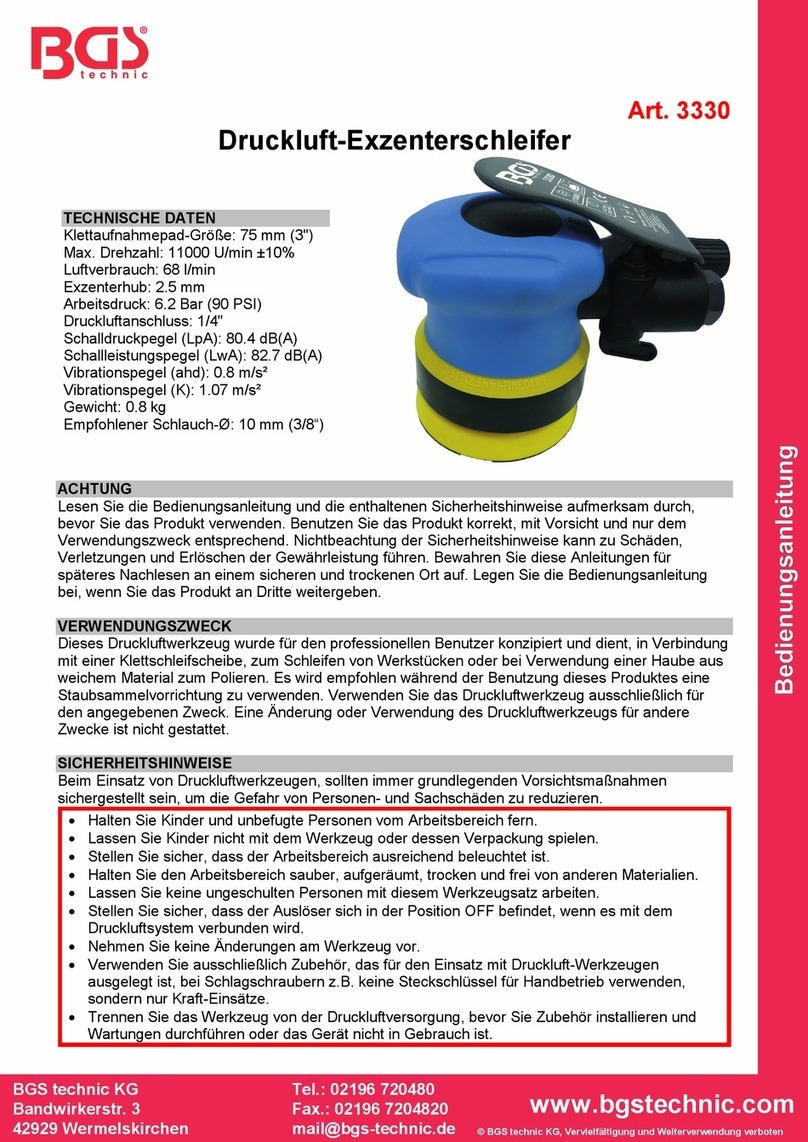
Druckluft-Handbandschleifer
SPEZIFIKATIONEN
Schleifbandgröße: 330 x 10 mm
max. Drehzahl: 16000 U/min
Luftverbrauch: 170 l/min
Arbeitsdruck: 6,3 bar
Druckluftanschluss: 1/4"
Gewicht: 1,2 kg
Abmessungen: 310 x 85 x 50 mm
max. Schalldruck: LpA: = 93 dB(A)
LwA: = 104 dg(A)
Vibration: ahd = 4,8 m/s²
ACHTUNG!
Lesen, verstehen und befolgen Sie alle Anweisungen und Warnungen vor und bei der
Inbetriebnahme dieses Druckluftgerätes. Falsche Handhabung und Missachtung der
Sicherheitshinweise können Verletzungen und Sachschäden verursachen und zum Erlöschen der
Garantie führen.
Vor dem ersten Gebrauch das Druckluftgerät mit 4 bis 5 Tropfen Druckluftgeräte-Öl schmieren.
Nur mit Druckluftsystemen betreiben, die über einen korrekten Luftdruck und ausreichend
Luftvolumen (L/min) für dieses Werkzeug verfügen.
WICHTIGE SICHERHEITSINFORMATIONEN
1. Stellen Sie sicher, dass das Werkzeug sich in der Position OFF befindet, wenn es mit dem
Druckluftsystem verbunden wird.
2. Vermeiden Sie unbeabsichtigtes Anlaufen des Werkzeugs. Tragen Sie das Werkzeug nicht mit
dem Finger am Abzug.
3. Tragen Sie bei Verwendung von Druckluft-Werkzeugen immer eine seitlich geschlossene,
zugelassene Schutzbrille, Sicherheitshandschuhe und verwenden Sie eine geeignete
Atemschutzmaske wenn Staub aufgewirbelt wird.
4. Verwenden Sie ausschließlich Zubehör, das für den Einsatz mit Druckluftferäten ausgelegt ist.
5. Trennen Sie das Werkzeug von der Druckluftversorgung, bevor Sie Zubehör installieren,
Wartungen durchgeführen oder das Gerät nicht in Gebrauch ist.
6. Betreiben Sie das Werkzeug immer mit gesundem Menschenverstand.
7. Tragen Sie keine weite Kleidung oder Schmuck die von beweglichen Teilen erfasst werden und zu
Verletzungen führen können.
8. Betreiben Sie das Werkzeug nur in sicherer Entfernung von sich selbst und anderen.
9. Verwenden Sie diesen Druckluft-Handbandschleifer nur an Druckluftanlagen die über eine
Wartungs- / Öler- Einheit verfügen.

LUFTVERSORGUNG
Saubere Luft und korrekter Luftdruck ist für die Versorgung dieses Werkzeugs unumgänglich. Der
maximale Druck für dieses Werkzeug liegt bei 6,3 bar und ist für die meisten Druckluft-Werkzeuge
dieser Klasse empfohlen. Dem Abschnitt Spezifikationen können alle Daten entnommen werden. Eine
Erhöhung des Luftdrucks ist erforderlich, wenn Länge des Luftschlauchs oder andere Umstände zu
einer Minderung des Luftdrucks führen. So muss der Luftdruck von 6,3 eventuell auf 7,2 bar erhöht
werden um einen Druck von 6,3 bar bei laufendem Werkzeug zu gewährleisten. Wasser im Schlauch
und Kompressor führt zur Reduzierung der Leistungsfähigkeit und Beschädigung der Druckluft-
Geräte. Entwässern Sie das Druckluft-System vor jedem Gebrauch.
Verwenden Sie einen Druckregler mit Manometer, wenn der Druck zu hoch ist.
Darstellung einer empfohlener Druckluftanlage
1 Werkzeug
6
Absperrventil
1
1 Lufttrockner
2 Druckluftschlauch
7
Flexibler Schlauch
1
2 Leitung 1“ oder größer
3 Öler (erforderlich)
8
Anschluss
1
3 Kompressor
4 Druckregler
9
Entwässerungsventil
1
4 Autom. Entwässerung
5 Filter
1
0 Leitung 1/2“ oder größer
1
5 Entwässerungsventil
SCHMIERUNG & WARTUNG
Druckluftgerät nur an Druckluftsystem betreiben die über einen automatischen Öler verfügen
Den im Abschnitt „Spezifikationen“ angegebenen maximalen Druck nicht übersteigt.
Vor dem ersten Gebrauch 4 bis 5 Tropfen Druckluftgeräte-Öl in den Lufteinlass geben.
Entwässern Sie das Druckluft-System vor jedem Gebrauch.
Wasser in der Druckluftleitung führt zu Zerstörung des Werkzeugs und zu Leistungsverlust.
Reinigen bzw. tauschen Sie Luftfilter im vorgeschriebenen Intervallen aus.
Öl für
Druckluftgeräte

SW-Stahl und Werkzeugvertriebs GmbH Tel. +49 (0) 2191 / 46438-0
F56essartSresukreveL ax +49 (0) 2191 / 46438-40
ed.lhatsws@ofni:liaM-EdiehcsmeR79824-D
Instruction Manual
BGS technic KG
Bandwirkerstr. 3
42929 Wermelskirchen
Tel.: 02196 720480
Fax.: 02196 7204820
www.bgstechnic.com
© BGS technic KG, Copying and further use not allowed
Art. 8853
Air Belt Grinder
SPECIFICATIONEN
Abrasive belt size: 330 x 10 mm
Speed: 16000 rpm
Air consumption: 170 l/min
Working pressure: 6.3 bar
Air inlet: 1/4"
Weight: 1.2 kg
Dimension: 310 x 85 x 50 mm
Noise Level: LpA: = 93 dB(A)
LwA: = 104 dg(A)
Vibration Level: ahd = 4.8 m/s²
IMPORTANT SAFETY INFORMATION
WARNING!
Read and understand and follow all instructions and warnings before operating this tool.
Failure to do so may result in personal injury and/or property damage and will void warranty.
Before first use, lubricate the air tool with 4 to 5 drops of pneumatic equipment oil.
Use proper air pressure and CFM rating listed for this tool.
1. Be sure air tool is in OFF position when connecting tool to air supply.
2. Avoid unintentional starting of the tool. Do not carry the tool with a finger on the trigger.
3. Always wear approved eye protection when using tools. If raising dust, wear a suitable mask.
4. Use only those accessories that are designed for use with tools.
5. Be sure to disconnect tool from air supply before changing accessories, performing service on
tool, and when not in use.
6. As with any tool, use common sense when operating.
7. Do not wear loose clothing or jewelry that could become caught by moving parts, causing injury.
8. Operate tool a safe distance from yourself and others in the work area.
9. Device may only be operated with air maintenance unit incl. oiler

SW-Stahl und Werkzeugvertriebs GmbH Tel. +49 (0) 2191 / 46438-0
F56essartSresukreveL ax +49 (0) 2191 / 46438-40
ed.lhatsws@ofni:liaM-EdiehcsmeR79824-D
Instruction Manual
BGS technic KG
Bandwirkerstr. 3
42929 Wermelskirchen
Tel.: 02196 720480
Fax.: 02196 7204820
www.bgstechnic.com
© BGS technic KG, Copying and further use not allowed
AIR SOURCE
Clean air of correct air pressure is recommended for the power supply for this tool. A maximum of 90
PSI at the tool is recommended for most air tools of this class. Check specifications section for
recommended pressure. Depending on length of air hose and other circumstances, air pressure at
compressor may need to be increased to 100 PSI to ensure 90 PSI at the tool. Water in the air hose
and compressor tank contributes to reduced performance and damage of the air tool. Drain the air
tank and filters before each use and as necessary to keep the air supply dry. Hose length over 25”
causes loss in line pressure. Increase hose ID or increase compressor pressure to compensate
for the pressure loss. Use an in-line pressure regulator with gauge if air inlet pressure is critical.
Recommended air compressor unit
1 Tool
6
Shut Off Valve
1
1
Air Dryer
2 Air Hose
7
Whip Hose
1
2
1“ Or Larger Pipe
3 Oiler (required)
8
Connector
1
3
Air Compressor
4 Pressure Regulator
9
Drain Valve (Drain Daily)
1
4
Auto Drain
5 Filter
1
0
½“ or Larger Pipe
1
5
Drain Valve (Drain Daily)
LUBRICATION & MAINTENACE
Only operate unit on compressed air system that equipped an automatic oiler.
Do not exceed maximum pressure which is described under "Specifications" section.
Before first use give 4-5 drops of pneumatic equipment oil into the air inlet.
Drain the water from the compressed air system before each use.
Water in air line or compressor can be lead to destruction of the air tool and power loss.
Clean or replace air filters in the prescribed intervals.
Oil for
Air tools

Kopfwinkel-Justierung:
1. Lösen Sie die
Klemmschraube
2. Stellen Sie den gewünschten
Winkel ein
3. Ziehen Sie die
Klemmschraube an
Head angle adjustment:
1. Loosen the clamping screw
2. Adjust the desired angle
3. Tighten the clamping screw
Schleifband wechseln:
1. Drücken Sie das
Spannelement zusammen
(Abb.1)
2. Legen Sie das Schleifband
über das Antriebsrad (Abb.2)
3. Legen Sie dann das
Schleifband über die
Spannrolle (Abb.3)
4. Entriegeln Sie das
Spannelement durch Drücken
auf den vorderen Teil der
Sperrklinge (Abb.4)
Grinding belt replacing:
1. Compress tensioning unit
(Fig.1)
2. Place the grinding belt onto
the drive wheel (Fig.2)
3. Place the grinding belt onto
the tensioning pulley (Fig.3)
4. Unlock the tensioning unit by
pressing the front part of the
locking jack (Fig.4)
1
2
3
4

SW-Stahl und Werkzeugvertriebs GmbH Tel. +49 (0) 2191 / 46438-0
F56essartSresukreveL ax +49 (0) 2191 / 46438-40
ed.lhatsws@ofni:liaM-EdiehcsmeR79824-D
CE-Erklärung
BGS technic KG
Bandwirkerstr. 3
42929 Wermelskirchen
Tel.: 02196 720480
Fax.: 02196 7204820
www.bgstechnic.com
EU-Konformitätserklärung
EC DECLARATION OF CONFORMITY
DÉCLARATION „CE“ DE CONFORMITE
DECLARATION DE CONFORMIDAD UE
Wir erklären in alleiniger Verantwortung, dass die Bauart der:
We declare that the following designated product:
Nous déclarons sous propre responsabilité que ce produit:
Declaramos bajo nuestra sola responsabilidad que este producto:
Druckluft-Bandschleifer ( BGS Art. 8853 )
Air belt sander
Ponceuse à bandes pneumatique
Lijadora de banda neumática
folgenden einschlägigen Bestimmungen entspricht:
complies with the requirements of the:
est en conformité avec les réglementations ci-dessous:
esta conforme a las normas:
Machinery Directive 2006/42/EC
Angewandte Normen:
Identification of regulations/standards:
Norme appliquée:
Normas aplicadas:
EN ISO 11148-8:2011
Verification-No: SH12111315-V1/AT-480
Test Report: SH12111315-001
Wermelskirchen, den 30.09.2014
ppa.
Frank Schottke, Prokurist
BGS technic KG, Bandwirkerstrasse 3, D-42929 Wermelskirchen
Other manuals for 8853
1
Table of contents
Languages:
Other BGS technic Grinder manuals

BGS technic
BGS technic 3287 User manual

BGS technic
BGS technic 3271 User manual

BGS technic
BGS technic 3287 User manual

BGS technic
BGS technic 9258 User manual

BGS technic
BGS technic 3264 User manual

BGS technic
BGS technic 3264 User manual

BGS technic
BGS technic BGS 3200 User manual

BGS technic
BGS technic 3269 User manual

BGS technic
BGS technic 3331 User manual

BGS technic
BGS technic 9657 User manual