BFM Europe Distinction Mounting instructions

Da Vinci &
Distinction
LOG EFFECT BALANCED FLUE ROO HEATER
Installation, aintenance & User Instructions
Hand these instructions to the user
odel No. BDVL**RN is for use on Natural Gas (G20) at a supply pressure of
20 mbar in G.B. / I.E.
** Denotes cosmetic variant

CONTENTS
PAGE
Section 1 Information and Requirements
1.0 Appliance information 3
1.1 Conditions of installation 4
1.2 Fireplace surround & suitability 4
1.3 Flue terminal position 5
Section 2 Installation of Fire
2.1 Unpacking the combustion chamber / surround / flue kit 6-7
2.2 Preparing the combustion chamber opening (In studded wall) 8
2.3 Preparing the combustion chamber opening (In chimney breast) 9-10
2.4 Installation of the gas supply 11
2.5 Specifying the flue system & components 12
2.6 Balanced flue in horizontal flue configuration 13-14
2.7 Balanced flue in vertical flue configuration 15
2.8 Balanced flue in vertical flue configuration (flat roof) 15-16
2.9 Balanced flue in vertical flue configuration (pitched roof) 17
2.10 Balanced flue utilising existing chimney 18-19
2.11 Securing the combustion chamber in the opening / fitting the closure plate 20
2.12 Setting hearth panel / surround legs / combustion chamber height 21-22
2.13 Installing the Da Vinci / Distinction surround design 23
2.14 Removal / Re-fitting the glass frame assembly 24-26
Section 3 Assembling Fuel Bed and Commissioning
3.1 Fitting the fuel bed logset 27-32
3.2 Making the gas conection & checking for gas tightness 33
3.3 Fitting the correct size of restrictor plate 33
3.4 Replacing the glass assembly 34
3.5 ighting the appliance 35-39
3.6 Fitting the handset wall bracket 39
3.7 Instruct user of fire operation 39
Section 4 aintenance
4.1 Removal of the burner assembly 40
4.2 Removal of the injector 40-41
4.3 Removal of the gas control valve / controls access cover 41
4.4 Removal of the ultrasonic receiver 42
4.5 Removal of the pilot assembly 42
4.6 Removal / Replacement of batteries in the Ultrasonic Receiver 42
4.7 Removal / Replacement of the handset battery 42
4.8 Parts shortlist 43
Section 5 User Instructions
5.1 Installation Information / About your fire 44-45
5.2 ighting the appliance 46-50
5.3 Cleaning instructions 50-53
5.4 Removing & replacing the logset 54-59
5.5 Replacing the glass assembly 60
5.6 User replaceable parts 61
odel number BDVL**RN is manufactured by:-
BFM Europe td, Trentham akes, Stoke-on-Trent, Staffordshire, ST4 4TJ
2

SECTION 1
INFOR ATION AND REQUIRE ENTS
1.0 APPLIANCE INFOR ATION
Main injector : (1 off) Bray Injector Cat 82 – size 600
Pilot Type : S.I.T. 140 Series – size 27
Max. Gross Heat Input : 8.7kW
Min. Gross Heat Input : 5.5 kW
Gas Rate : 0.799 m3/hr (High)
0.511 m3/hr ( ow)
Cold Pressure : G20 20.0+/-1.0 mbar (8.0 +/- 0.4 in w.g.)
Ignition : Via remote handset, integral to gas valve
Electrode Spark Gap : 4.0mm
NOx evel Class 5
Packed Weight Combustion Chamber 57.0 kg (Pack 1 of 3)
Appliance Efficiency Declaration
The efficiency of this appliance has been measured as specified in BS EN 613 : 2001 and
the result is 74%. The gross calorific value of the fuel has been used for this efficiency
calculation. The test data from which it has been calculated has been certified by G
Industrial Services UK td. The efficiency value may be used in the UK Government’s
Standard Assessment Procedure (SAP) for energy rating of dwellings.
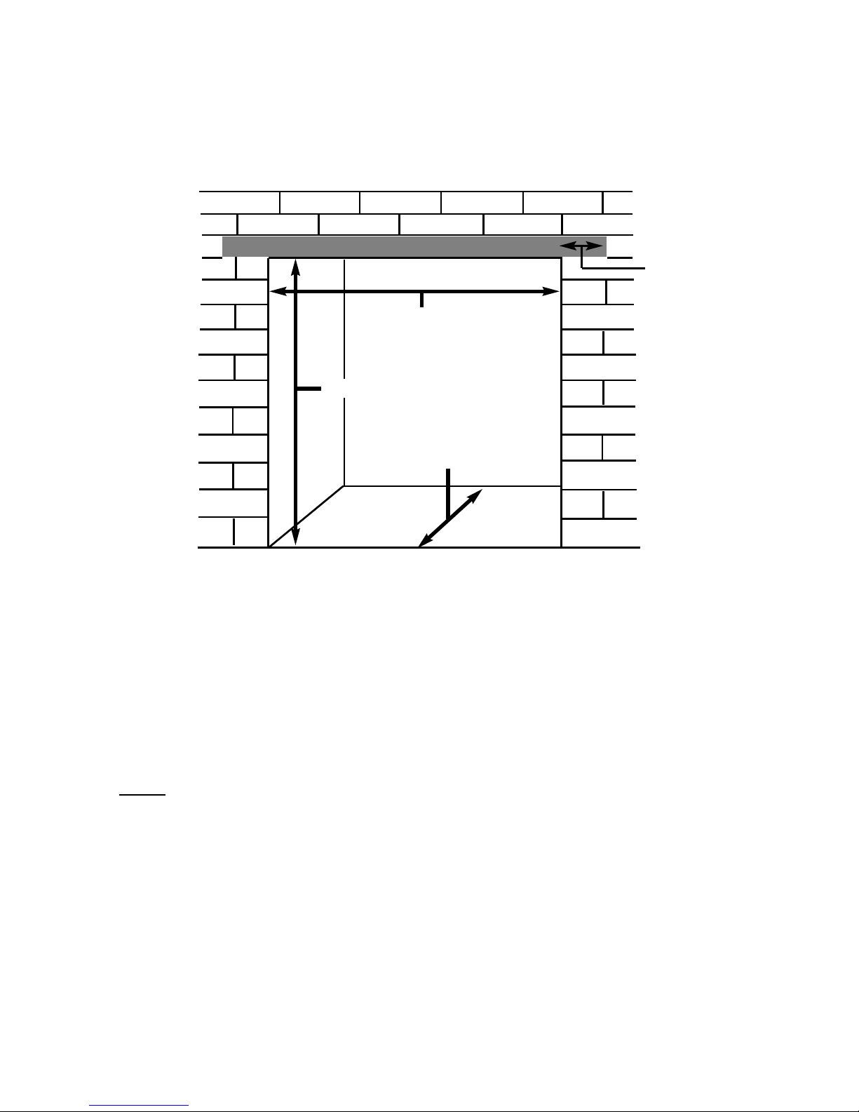
Fig 1 Fig. 2
Top View of Combustion Side View of Combustion
Chamber Chamber
3
930mm
747 mm
384 mm 150mm
Diameter
75mm
Diameter
100mm
134mm CRS
384mm
49mm
360mm
767mm
360mm

INSTALLATION REQUIRE ENTS
1.1 CONDITIONS OF INSTALLATION
It is the law that all gas appliances are installed only by a GAS SAFE Registered
Installer, in accordance with these installation instructions and the Gas Safety
(Installation and Use) Regulations 1998 as amended. Failure to install appliances
correctly could lead to prosecution. It is in your own interest and that of safety to
comply with the law.
The installation must also be in accordance with all relevant parts of the ocal and
National Building Regulations where appropriate, the Building Regulations
(Scotland Consolidation) issued by the Scottish Development Department, and all
applicable requirements of the following British Standard Code of Practice.
1. B.S. 5871 Part 1 Installation of Gas Fires
2. B.S. 6891 Installation of Gas Pipework
3. B.S. 5440 Parts 1 & 2 Installation of Flues and Ventilation
4. I.S 813 : 1996 Domestic Gas Installation, issued by the National Standards
Authority of Ireland.
1.2 FIREPLACE / SURROUND SUITABILITY
The fire must only be installed on a hearth it must not be installed directly onto
carpet or other combustible floor materials.
The fire is suitable for fitting to non-combustible fire place surrounds and
proprietary fire place surrounds with a temperature rating of at least 150oc.
If a heating appliance is fitted directly against a wall combustible material must be
removed from behind it. Soft wall coverings such as blown vinyl, wall paper etc.
could be affected by the rising hot air and scorching and/or discoloration may
result. Due consideration should be made to this when installing or decorating.
It is recommended that the product is only installed with surround designs
available from BF Europe Ltd, but should you choose to fit an alternative
surround, please give consideration to accessibility for servicing
requirements
4

1.3 FLUE TER INAL POSITION
The minimum acceptable dimensions from the flue terminal to obstructions
and ventilation openings are shown below and listed in the table
It is important that the position of the flue allows the free passage of air
across it at all times. The minimum acceptable space from the flue terminal
to obstructions and ventilation openings are specified below (Fig. 3)
Fig. 3
DI ENSION TER INAL POSITION INI U DI ENSION
A Directly below an opening, air brick, 300mm (12in)
opening window
B Above an opening, air brick, 300mm (12in)
opening window
C Horizontally to an opening, air brick,
opening window etc.
D Below gutters, soil pipes or drain pipes 300mm (12in)
E Below eaves 300mm (12in)
F Below balconies or car port roof 600mm (12in)
G From a vertical drain pipe or soil pipe 300mm (12in)
H From an internal or external corner 600mm (24in)
I Above ground roof or balcony level 300mm (12in)
J From a surface facing the terminal 600mm (24in)
K From a terminal facing the terminal 600mm (24in)
L From an opening in the car port 1200m (48in)
Vertically from a terminal on the same wall 1500mm(59in)
N Horizontally from a terminal on the 300mm (12in)
same Wall
O NOT APPLICABLE N/A
P NOT APPLICABLE N/A
Q NOT APPLICABLE N/A
5

SECTION 2
INSTALLATION OF FIRE
2.1 UNPACKING THE CO PONENTS
Remove the loose item packaging carefully from the pack. Check the contents as
listed :-
DO NOT UNDER ANY CIRCU STANCES USE THIS APPLIANCE IF THE GLASS PANEL IS BROKEN
OR NOT SECURELY FIXED TO THE FIREBOX.
Packing Check ist
Pack 1 of 3 - Combustion Chamber Pack
1 off Combustion chamber & glass frame assembly
1 off Boxed ceramic fuel-bed set (packed inside combustion chamber)
1 off Installation / user instruction manual
1 off Top closure plate
1 off oose items pack – containing :- 1 off 9V battery, 4 off 1.5V batteries
Remote handset, 4 off M5 locknuts
3 off restrictor plates & fixing screws
1 off handset wall brkt (inc. fixings)
1 off glass removal tool
Pack 2 of 3 - Horizontal Balanced Flue System Pack
1 off Adaptor 1 off 0.5m length of flue
1 off 90 degree elbow 1 off Horizontal wall terminal
2 off ocking bands 1 off Protection band
or
Pack 2 of 3 - Chimney Conversion Kit
1 off Adaptor 1 off 1.0m length of flue
1 off Renovation kit 1 off Vertical terminal
1 off ocking band
or
Pack 2 of 3 - Vertical Flue Kit
1 off Adaptor 1 off Vertical terminal
In addition, all flue lengths, roof flashing, clamps and accessories as required by
the individual flue system design should be purchased as required from the
manufacturer, contact details as per overpage
6

Carefully lift the surround components out of the wooden crate. Remove the loose
item packaging carefully from the pack. Check the contents as listed below :-
Pack 3 of 3 - Da Vinci Surround
1 off Hearth 1 off /H leg
1 off Shelf 1 off R/H leg
1 off Top infill 1 off Controls access panel
1 off Shelf infill section
or
Pack 3 of 3 - Distinction Surround
1 off Hearth 1 off /H leg
1 off Shelf 1 off R/H leg
1 off Top infill 1 off Controls access panel
1 off Shelf infill section
7

2.2 PREPARATION OF THE CO BUSTION CHA BER OPENING
(INTO STUDDED WALL)
All combustible parts of the studwork must be set at the distances as shown below
in Fig. 4 & 5.
Refer to Fig. 1 on page three for dimensions of the flue outlet.
8
Minimum 50mm at sides
Minimum 50mm at rear
Combustion Chamber
Fig. 4
Fig. 5
A minimum clearance of
100mm is required above
the top of the flue pipe to
combustible surfaces
Width = 870mm
Height = 955mm
Depth = 439mm
NOTE : Dimensions as stated above
include clearance to combustible stud
work
2.3 PREPARATION OF THE CO BUSTION CHA BER OPENING
(INTO EXISTING CHI NEY BREAST)
An opening should be constructed to the following dimensions in the existing
chimney breast.
Fig. 5
The opening needs to be sufficient to accomodate the combustion chamber. To
support the wall above the opening, a suitable lintel must be inserted across the
top of the opening. The lintel could be either pre-cast concrete or steel - Catnic
CN52 or CN 46 could be used, depending upon the inner wall thickness. Before
proceeding with the installation of the fire, an assessment of the area immediately
above the fire is required, see Fig. 9 overpage. If there is no existing openings
within either triangle, proceed with forming the opening. However, if opening or
beams occur within either triangle, then you should seek specialist advice from a
structural engineer or consider relocating the proposed position of the firebox.
NOTE : Please ensure that suitable cut outs in the sides and front face of the
chimney breast are implemented for fixing of the flue pipe, and for future
servicing.
The appliance must be sited on a non combustible base. The appliance can be
placed onto a combustible material providing a heatproof board such as superlux
of minimum 15mm thickness or similar is placed under it.
I PORTANT : Any air supply to the fireplace opening must be sealed off
9
Minimum Depth 390mm
intle must
project 150mm
either side of the
opening if
cutting into an
existing chimney
breast
Width = 870mm
Height = 955mm

2.3 (CONTINUED)
Fig. 9
10
400mm interactive area
600mm load triangle
The Interactive Zone -
Openings, beams or joists within
this area need to be assessed.
oad triangle - No beam or
opening permissible within this
area
intel
e.g. 750mm x 75mm
Proposed Opening in
Chimney Breast
Minimum 200mm
150mm
This manual suits for next models
1
Table of contents
Other BFM Europe Gas Heater manuals


Popular Gas Heater manuals by other brands

Superior
Superior BGE18NV Installation and operation instructions

Dru
Dru Room-sealed atmospheric gas-fired heating... user manual

klover
klover TKR 35 user guide

Rothenberger Industrial
Rothenberger Industrial 035984 instruction manual

New Buck Corporation
New Buck Corporation 34 user manual

Hargrove
Hargrove Timberland Glow Operation and installation guide


Superior
Superior BGE18NR Operation instructions

Brant Radiant Heaters
Brant Radiant Heaters QTD Series User instruction

L.B. White
L.B. White Therma Grow HW220 Owner's manual and instructions

Sealey
Sealey LP35.V5 instructions

Italkero
Italkero Falo Evo User manual and assembly instructions

Desa
Desa 30LP owner's manual