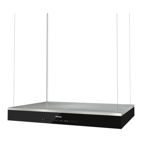
Best IS170 User manual

ENGLISH......................................3
FRANÇAIS..................................15
ESPAÑOL...................................27
Model IS170
In USA - BEST Hartford, Wisconsin
In CANADA - BEST Drummondville, QC, Canada
REGISTER YOUR PRODUCT ONLINE AT : www.BestRangeHoods.com/register
For additional Information visit www.BestRangeHoods.com


- 3 -
READ AND SAVE THESE INSTRUCTIONS
WARNING
TO REDUCE THE RISK OF FIRE, ELECTRIC SHOCK, OR INJURY TO PERSONS,
OBSERVE THE FOLLOWING:
1. Use this unit only in the manner intended by the manufacturer. If you have questions,
contact the manufacturer at the address or telephone number listed in the warranty.
2. Before servicing or cleaning unit, switch power off at service panel and lock service
panel to prevent power from being switched on accidentally. When the service
disconnecting means cannot be locked, securely fasten a prominent warning device,
such as a tag, to the service panel.
3. Installation work and electrical wiring must be done by a qualified person(s) in accor-
dance with all applicable codes and standards, including fire-rated construction codes
and standards.
4. Sufficient air is needed for proper combustion and exhausting of gases through the flue
(chimney) of fuel burning equipment to prevent backdrafting. Follow the heating equip-
ment manufacturer’s guidelines and safety standards such as those published by the
National Fire Protection Association (NFPA), and the American Society for Heating,
Refrigeration and Air Conditioning Engineers (ASHRAE), and the local code authorities.
5. When cutting or drilling into wall or ceiling, do not damage electrical wiring and other
hidden utilities.
6. Ducted fans must always be vented to the outdoors.
7. Do not use this unit with any separate solid-state speed control device.
8. To reduce the risk of fire, use only metal ductwork.
9. This unit must be grounded.
TO REDUCE THE RISK OF A RANGE TOP GREASE FIRE:
A. Never leave surface units unattended at high settings. Boilovers cause smoking and
greasy spillovers that may ignite. Heat oils slowly on low or medium settings.
B. Always turn hood ON when cooking at high heat or when flambeing food (i.e. Crepes
Suzette, Cherries Jubilee, Peppercorn Beef Flambe’).
C. Clean ventilating fans frequently. Grease should not be allowed to accumulate on fan or
filter.
D. Use proper pan size. Always use cookware appropriate for the size of the surface
element.
WARNING
TO REDUCE THE RISK OF INJURY TO PERSONS IN THE EVENT OF A RANGE TOP
GREASE FIRE, OBSERVE THE FOLLOWING:*
1. SMOTHER FLAMES with a close-fitting lid, cookie sheet, or metal tray, then turn off the
burner. BE CAREFUL TO PREVENT BURNS. If the flames do not go out immediately,
EVACUATE AND CALL THE FIRE DEPARTMENT.
2. NEVER PICK UP A FLAMING PAN - You may be burned.
3. DO NOT USE WATER, including wet dishcloths or towels - violent steam explosion will
result.
4. Use an extinguisher ONLY if:
A. You know you have a Class ABC extinguisher and you already know how to operate
it.
B. The fire is small and contained in the area where it started.
C. The fire department is being called.
D. You can fight the fire with your back to an exit.
* Based on “Kitchen Fire Safety Tips” published by NFPA.
!
INTENDED FOR DOMESTIC COOKING ONLY
!

- 4 -
!
CAUTION
1. For indoor use only.
2. To reduce risk of fire and to properly exhaust air, be sure to duct air outside. Do not vent
exhaust air into spaces within walls or ceilings or into attics, crawl spaces, or garages.
3. Take care when using cleaning agents or detergents.
4. Avoid using food products that produce flames under the Range Hood.
5. For general ventilating use only. Do not use to exhaust hazardous or explosive materi-
als and vapors.
6. To avoid motor bearing damage and noisy and/or unbalanced impellers, keep drywall
spray, construction dust, etc. off power unit.
7. Your hood motor has a thermal overload which will automatically shut off the motor if it
becomes overheated. The motor will restart when it cools down. If the motor continues
to shut off and restart, have the hood serviced.
8. For best capture of cooking impurities, the bottom of the hood should be a minimum of
24" and a maximum of 30" above the cooking surface.
9. Two installers are recommended because of the large size and weight of this hood.
10. This product is equipped with a thermostat which may start blower automatically. To
reduce the risk of injury and to prevent power from being switched on accidentally,
switch power off at service panel and lock or tag service panel.
11. Use with approved cord-connection kit only.
12. Please read specification label on product for further information and requirements.

PREPARE THE HOOD
Unpack hood and check contents.
You should receive:
1 - Hood
1 - Decorative Flue Assembly
1 - Support Frame
1 - Glass Frame (Optional)
1 - Parts Bag (B080810504) containing:
4 - Mounting Screws (6 x 70mm)
4 - Washers
8 - Mounting Screws (3,9 x 9,5mm Pan Head)
3 - Glass Brackets
8 - Brackets Mounting Screws (3,9 x 6mm)
6 - Glass Mounting Screws (M4 x 20mm)
6 - Glass Adhesive Pads
1 - Installation Instructions
4 MOUNTING
SCREWS
(6x70mm)
SUPPORT
FRAME
DECORATIVE
FLUE GLASS FRAME
(Optional)
4 WASHERS
8 MOUNTING
SCREWS
(3,9x9,5mm
Pan Head)
3 GLASS
BRACKETS
6 GLASS
MOUNTING
SCREWS
(M4x20mm)
6 GLASS
ADHESIVE
PADS
8 BRACKETS
MOUNTING
SCREWS
(3,9x6mm)

- 6 -
MOUNTING
SCREWS
(6x70mm)
INSTALL THE DUCTWORK
NOTE: To reduce the risk of fire, use only
metal ductwork.
1.Decide where the ductwork will run between
the hood and the outside.
2. A straight, short duct run will allow the hood
to perform most efficiently.
3. Long duct runs, elbows, and transitions will
reduce the performance of the hood. Use
as few of them as possible. Larger ducting
may be required for best performance with
longer duct runs.
4. Install a roof or wall cap. Connect round
metal ductwork to cap and work back to-
wards hood location. Use duct tape to seal
the joints between ductwork sections.
HOOD
ROUND
ELBOW
ROUND
DUCT
ROOF CAP
DECORA-
TIVE
FLUE
TOP VIEW OF SUPPORT FRAME
24” TO 30” ABOVE
COOKING SURFACE
SUPPORT
FRAME
OPENINGS
EAVE
VENT
CROSS FRAMING
9-13/16”
9-13/16”
INSTALL SUPPORT SYSTEM
1. At hood location, install 2 x 4 cross framing
between ceiling joists using dimensions
shown on center.
2. Finish the ceiling surface. Be sure to mark
the location of the ceiling joists and cross
framing.
3. Position the support frame as shown. The
UP ARROW should point towards the
ceiling after installation.
4. Secure the support frame to joists and cross
framing with four screws (6x70mm) and
washers provided. Make sure screws are
driven into center of joists and framing for
maximum strength.
5. Adjust the overall height of the support
frame. Loosen and re-tighten the screws
in the height adjustment slots as
necessary. Note that the hood height is 14-
3/16” (360mm) and that the bottom of the
hood must be 24” min. and 30” max. above
the cooktop.
6” ADAPTER
CEILING
JOISTS
CROSS FRAMING
HEIGHT
ADJUSTMENT
SLOTS
SUPPORT
FRAME
913/16”
DRYWALL
WASHERS
(Ø6.4mm)
FRONT

- 7 -
14-3/16”
min 24”
max 30”
HEIGHT
ADJUSTEMENT
SLOTS
CONNECT DECORATIVE FLUE
1. Secure the upper flue to the support frame
with the mounting screws 3.9x6mm (air
vents must be up).
2. Insert the lower flue moving it completely
towards the top and fix it temporarily with
mounting screws (3.9x6mm).
UPPER FLUE
MOUNTING
SCREWS
(3.9x9.5mm)
RETAINING
SCREWS
(3.9x6mm)
LOWER FLUE

- 8 -
Non-ducted recirculation configuration
Purchase a Non-ducted recirculation KIT
from your dealer (Model NDIS170).
1. Insert the non-ducted recirculation plenum
through the support frame openings.
Secure the non-ducted recirculation
plenum using two (2) brackets and four (4)
mounting screws (3.9x9.5mm).
Fix a flexible duct to the duct connector of
the non-ducted recirculation plenum.
2. Secure the upper flue to the support frame
with the mounting screws 3.9x9.5mm (air
vents must be up).
3. Insert the lower flue moving it completely
towards the top and fix it temporarily with
mounting screws (3.9x6 mm).
UPPER FLUE
MOUNTING
SCREWS
(3.9x9.5mm)
RETAINING
SCREWS
(3.9x6mm)
LOWER FLUE
NON-DUCTED
RECIRCULATION
PLENUM
FLEXIBLE
DUCT
DUCT
CONNECTOR
BRACKETS
MOUNTING
SCREWS
(3.9x9.5mm)

- 9 -
INSTALLATION OF GLASS
FRAME (Optional)
Purchase a Glass Frame from your dealer
(Model GSIS170).
1. Fit the glass frame above the hood.
2. Fit the supplied adhesive pads on the glass
frame in correspondence to its fixing screws
in order to prevent the glass from breaking.
3. Fix the (3) supplied brackets to the hood
with mounting screws (3.9x6mm).
4. Adjust the position of the glass frame and
fix it by means the mounting screws
(M4x20mm).
Please be very careful not to hit the glass
with any objects made of porcelain, metal,
glass or anything else that is very heavy.
GLASS FRAME
SUPPLIED
BRACKETS ADHESIVE
PADS
MOUNTING SCREWS (M4x20mm)
CONNECT DUCTWORK
1. Position the hood near the lower part of
the support frame and connect the duct to
the duct collar.
2. Use 6" round metal duct to connect the
duct collar on the hood to the ductwork
above.
3. Use duct tape to make all joints secure and
air tight. DUCT 6”
DUCT COLLAR
MOUNTING SCREWS
(3.9x6mm)

- 10 -
MOUNT HOOD TO SUPPORT
FRAME
1. Install the hood to support frame by (6)
mounting screws (3.9x9.5mm), minding
that the controls are on the proper side.
2. Make electrical connections (refer to the
section “WIRING”).
3. Remove the two temporary fixing screws
of the lower flue and set it in place on the
hood.
MOUNTING
SCREWS
(3.9X9.5MM)
WIRING
Note: This range hood must be properly
grounded. The unit should be installed by a
qualified electrician in accordance with all
applicable national and local electrical
codes.
1. Remove the wiring box cover. Remove a
knockout from the wiring box.
2. Feed 6" of power cable through the knock-
out opening and secure cable to the wiring
box with an appropriate connector.
3. Make electrical connections. Connect
white to white, black to black and green to
green.
4. Replace wiring box cover and screws.
Make sure that wires are not pinched
between cover and box.
WIRING BOX
COVER
NON-DUCTED
RECIRCULATION FILTER
INSTALLATION
1. Purchase a charcoal filter (FILTER
SQUARE - cod.B03300488) from your
dealer.
2. Install the charcoal filter by pressing the 2
tabs on the filter down into the special
housing and rotating upward. CHARCOAL
FILTER
Table of contents
Languages:
Other Best Ventilation Hood manuals