Best CC34IQSB User manual

Model CC34IQSB
ENGLISH.....................................1
FRANÇAIS.................................17
ESPAÑOL..................................33
In USA - BEST Hartford, Wisconsin
In CANADA - BEST Drummondville, QC, Canada
REGISTER YOUR PRODUCT ONLINE AT : www.BestRangeHoods.com/register
For additional Information visit www.BestRangeHoods.com

- 2 -
READ AND SAVE THESE INSTRUCTIONS
WARNING
TO REDUCE THE RISK OF FIRE, ELECTRIC SHOCK, OR INJURY TO PERSONS, OBSERVE
THE FOLLOWING:
1. Use this unit only in the manner intended by the manufacturer. If you have questions, contact
the manufacturer at the address or telephone number listed in the warranty.
2. Before servicing or cleaning unit, switch power off at service panel and lock service panel
to prevent power from being switched on accidentally. When the service disconnecting means
cannot be locked, securely fasten a prominent warning device, such as a tag, to the service panel.
3. Installation work and electrical wiring must be done by a qualified person(s) in accordance with
all applicable codes and standards, including fire-rated construction codes and standards.
4. Sufficient air is needed for proper combustion and exhausting of gases through the flue (chimney)
of fuel burning equipment to prevent backdrafting. Follow the heating equipment manufacturer’s
guidelines and safety standards such as those published by the National Fire Protection
Association (NFPA), and the American Society for Heating, Refrigeration and Air Conditioning
Engineers (ASHRAE), and the local code authorities.
5. When cutting or drilling into wall or ceiling, do not damage electrical wiring and other hidden
utilities.
6. Ducted fans must always be vented to the outdoors.
7. Do not use this unit with any separate solid-state speed control device.
8. To reduce the risk of fire, use only metal ductwork.
9. This unit must be grounded.
10.Type Non-IC Installation:Thermal insulation shall not cover top of range hood housing and must
be spaced 3-inches (76mm) from all sides. (Fig. 1)
!
INTENDED FOR DOMESTIC COOKING ONLY
!
3-INCH MINIMUM.
NO INSULATION
WITHIN THIS SHADED
AREA OF COMPONENTS.
FIG. 1

- 3 -
!
CAUTION
1. For indoor use only.
2. To reduce risk of fire and to properly exhaust air, be sure to duct air outside. Do not vent exhaust
air into spaces within walls or ceilings or into attics, crawl spaces, or garages.
3. Take care when using cleaning agents or detergents.
4. Avoid using food products that produce flames under the Range Hood.
5. For general ventilating use only. Do not use to exhaust hazardous or explosive materials and vapors.
6. To avoid motor bearing damage and noisy and/or unbalanced impellers, keep drywall spray,
construction dust, etc. off power unit.
7. Your hood motor has a thermal overload which will automatically shut off the motor if it becomes
overheated. The motor will restart when it cools down. If the motor continues to shut off and
restart, have the hood serviced.
8. The minimum hood distance above the cooktop must not be less than 48". A maximum of 84"
above the cooktop is highly recommended for best capture of cooking impurities. Distances
over 84"are at the installer and user’s discretion.
9. Two installers are recommended because of the large size and weight of this hood.
10. The light source is designed for this specific application and can overheat if serviced by untrained
personnel. If any servicing is required, the product should be returned to an authorized service
facility for examination or repair.
11. Please read specification label on product for further information and requirements.
12. This power pack is equipped with a RF receiver (optional remote control sold separately).
Changes or modifications not expressly approved by the party responsible for compliance
could void the user’s authority to operate this product. The remote control has been tested
and found to comply with the limits for a Class B digital device, pursuant to part 15 of the FCC
Rules and the Canadian ICES-003.These limits are designed to provide reasonable protection
against harmful interference in a residential installation. The remote control generates, uses
and can radiate radio frequency energy and, if not installed and used in accordance with the
instructions, may cause harmful interference to radio communications. However, there is no
guarantee that interference will not occur in a particular installation.If this equipment does cause
harmful interference to radio or television reception, which can be determined by turning the
equipment off and on, the user is encouraged to try to correct the interference by one or more
of the following measures:
• Reorient or relocate the receiving antenna.
• Increase the separation between the equipment and receiver.
• Connect the equipment into an outlet on a circuit different from that to which the receiver
is connected.
13. When used in recirculation mode, To Reduce the Risk of Fire and Shock use only conversion
kit Model ANKCC34.
TO REDUCE THE RISK OF A RANGE TOP GREASE FIRE:
A. Never leave surface units unattended at high settings. Boilovers cause smoking and greasy
spillovers that may ignite. Heat oils slowly on low or medium settings.
B. Always turn hood ON when cooking at high heat or when flambeing food (i.e. Crepes Suzette,
Cherries Jubilee, Peppercorn Beef Flambe’).
C. Clean ventilating fans frequently. Grease should not be allowed to accumulate on fan or filter.
D. Use proper pan size. Always use cookware appropriate for the size of the surface element.
TO REDUCE THE RISK OF INJURY TO PERSONS IN THE EVENT OF A RANGE TOP GREASE
FIRE, OBSERVE THE FOLLOWING:*
1. SMOTHER FLAMES with a close-fitting lid, cookie sheet, or metal tray, then turn off the burner.
BE CAREFUL TO PREVENT BURNS. If the flames do not go out immediately, EVACUATE AND
CALL THE FIRE DEPARTMENT.
2. NEVER PICK UP A FLAMING PAN - You may be burned.
3. DO NOT USE WATER, including wet dishcloths or towels - violent steam explosion will result.
4. Use an extinguisher ONLY if:
A. You know you have a Class ABC extinguisher and you already know how to operate it.
B. The fire is small and contained in the area where it started.
C. The fire department is being called.
D. You can fight the fire with your back to an exit.
* Based on “Kitchen Fire Safety Tips” published by NFPA.

- 4 -
OPERATION
Controls (Fig. 2)
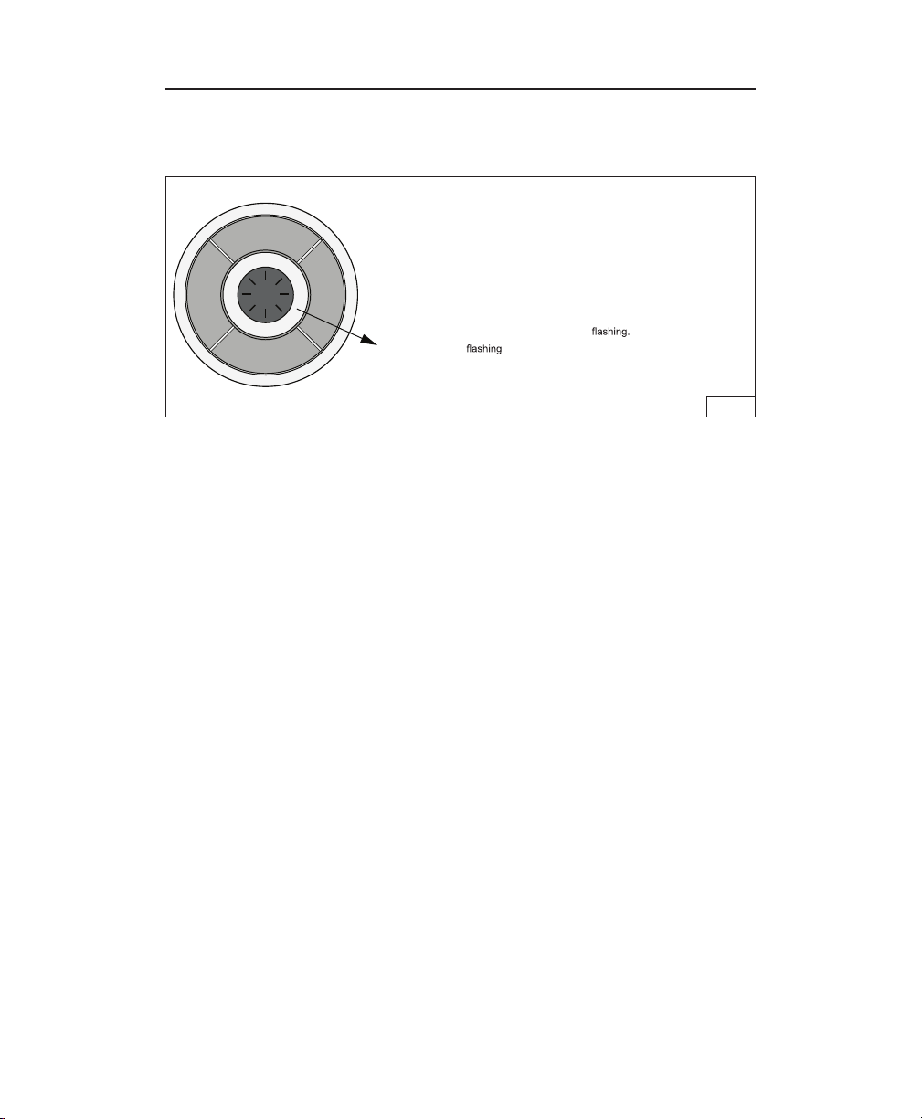
The hood is operated using the (5) push-buttons located on the hood and the remote control.
LED colors are displayed on hood control only.
FIG. 2
(P1) Delay- Off Switch
• Your hood includes a 10 minute blower delay off switch. Press this switch once to activate the
timer and the LED Ring (L1) flashes blue. The blower will continue to operate for 10minutes.
After 10 minutes, the blower turns off automatically.
• To cancel the 10-minute delay, press the delay switch once again.
(P2) Filter Alarm Switch
• After 30 hours of blower operation, the filter alarm is activated and the LED ring (L1) turns red/
flashes. It indicates that the grease filters need to be cleaned.
• After cleaning the grease filters, reset the hour counter by pressing the FilterAlarm/Timer Reset
button (P2) during display of the alarm.
(P3) Blower Speed Decrease and Off Switch
• Press to decrease blower speed, high to low. The LED ring (L1) flashes blue at a speed
proportionate to the blower setting (i.e.: four flashes is high speed, one flash is low speed, etc.)
• Continue pressing this switch to turn the blower off.
(P4) Blower Speed Increase and On Switch
• Press this switch to turn the blower on to low speed.
• Press again to increase blower speed, low to high. The LED ring (L1) flashes blue at a speed
proportionate to the blower setting (i.e.: four flashes is high speed, one flash is low speed, etc.)
(P5) Light Switch
Lights off/low/medium/high.
P1: Activate/deactivate delay-off (10 minute)
P2: Filter change indication timer reset
P3: Decreases fan motor speed until turned off (4>3>2>1>OFF)
P4: Turns fan motor on and increased speed (ON>1>2>3>4)
P5: Turns lights on/off
L1: LED Indicator Ring Signalling crown:
- Hood in standby: lights up 30 seconds after
the last key has been pressed the crown turns off
- Motor on: L1 lights up blue The
frequency is proportional to the speed setting.
- 10’ TIMER function : L1 lights up and flashes blue.
- Filter alarm active: L1 lights up red
L1
LED
RING
+
-
ƒ
¤
(P1)
(P2)
(P3)
(P4)
(P5)

- 5 -
HOOD
CONTROL
REMOTE CONTROL
The remote control is linked to the hood at the factory.
If, for some reason, the link is lost - follow the directions below:
To Link Remote Control to Hood
1. Turn off hood motor and hood lights.
2. Press and buttons on the remote simultaneously for 5 seconds, until the remote
control Indicator Light turns on (Fig.3). Release button.The indicator light will light up. (Fig. 3)
3. Within 3 seconds - press ƒ(P2) on the hood control. (Fig. 4) The LED ring will light up for
approximately 10 seconds to confim that the linking process was successful.
L1
LED
RING
+
-
ƒ
¤
(P1)
(P2)
(P3)
(P4)
(P5)
INDICATOR
LIGHT
FIG. 4
FIG. 3
Remote Control Functions (Fig.3)
Delay - Off
Blower Speed Decrease and Off
Blower Speed Increase and On
Light
Press (Delay) and (Light) together to Reset Filter Alarm.
IMPORTANT: Holding (Delay) for more than 3 seconds will cause the link between the
remote and hood to be lost.
- 23A +
See “Controls” section on previous page for
more information on each function.
Battery disposal
When the batteries need to be replaced, dispose of them only and exclusively in the numerous readily available
special waste bins, especially in shops selling electronic consumer goods. Observance of the regulations on
differentiated waste collection, in particular, proper disposal of used batteries, contributes to preventing possible
negative effects on the environment and health.

- 6 -
CLEANING AND MAINTENANCE
Proper maintenance of the Range Hood will assure proper performance of the unit.
Motor
The motor is permanently lubricated and never needs oiling. If the motor bearings make excessive or
unusual noise, replace the motor with the exact service motor.The impeller should also be replaced.
Grease Filters
The grease filters should be cleaned frequently. Use a warm detergent solution. Grease filters are
dishwasher safe.
Clean all-metal filters in the dishwasher using a non-phosphate detergent.Discoloration of the filter may
occur if using phosphate detergents, or as a result of local water conditions - but this will not affect filter
performance.This discoloration is not covered by the warranty.
See “INSTALL FILTERS” section for removal and installation instructions.
Stainless Steel Cleaning
DO:
• Regularly wash with clean cloth or rag soaked
with warm water and mild soap or liquid dish
detergent.
• Always clean in the direction of original polish
lines.
• Always rinse well with clear water (2 or 3 times)
after cleaning. Wipe dry completely.
• You may also use a specialized household
stainless steel cleaner.
DON’T:
•
Use any steel or stainless steel wool or any
other scrapers to remove stubborn dirt.
• Use any harsh or abrasive cleansers.
• Allow dirt to accumulate.
• Let plaster dust or any other construction
residues reach the hood. During construction/
renovation, cover the range hood to make sure
no dust sticks to the stainless steel surface.
Avoid:When choosing a detergent
• Any cleaners that contain bleach will attack stainless steel
• Any products containing: chloride, fluoride, iodide, bromide will deteriorate surfaces rapidly.
• Any combustible products used for cleaning such as acetone, alcohol, ether, benzol, etc., are highly
explosive and should never be used close to a range.

- 7 -
PREPARE THE HOOD
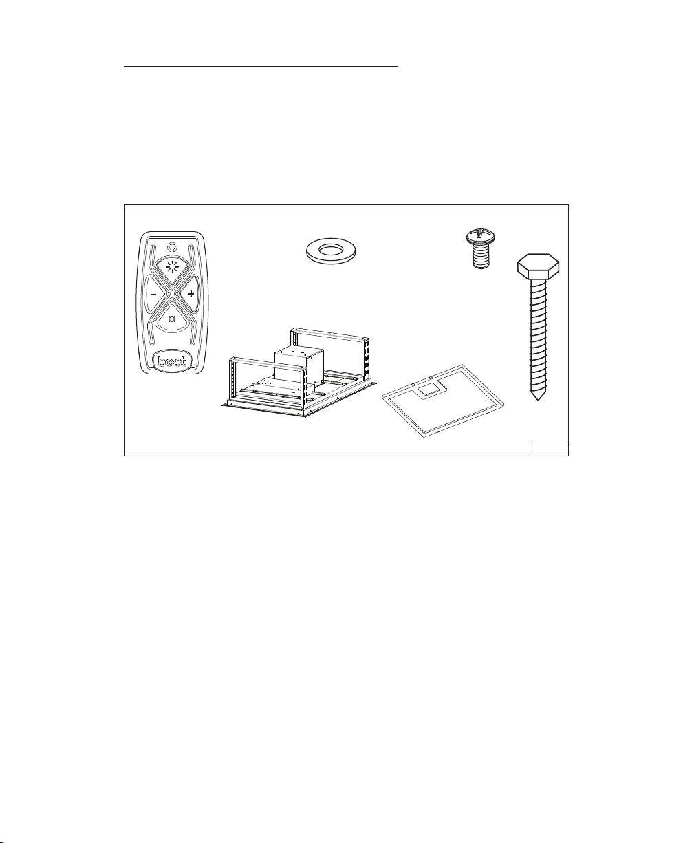
Unpack hood and check contents.
You should receive:
1 - Range Hood Body
1 - Remote Control
6 - Grease Filters
2 - Screws, 4 x 9.5 mm
6 - Lag Bolts, 6 x 70 mm
6 - Washers
6 LAG BOLTS
(6 x 70 mm)
FIG. 5
REMOTE
CONTROL
RANGE HOOD
BODY with DAMPER
6 GREASE
FILTERS
6 WASHERS
2 SCREWS
(4 x 9.5 mm)

- 8 -
INSTALL THE DUCTWORK
FIG. 6
ROOF CAP
48" TO 84" ABOVE
COOKING SURFACE
HOOD
8" ROUND
DUCT
8" ROUND
TO 3¼” X 14”
REDUCER
3¼” X 14”
UNDER
EAVE
VENT
8" ROUND
DUCT
WARNING: To reduce the
risk of fire, use only metal duc-
twork.
1. Decide where the ductwork will
run between the hood and the
outside. Fig. 6.
2. A straight, short duct run will
allow the hood to perform most
efficiently.
3. Long duct runs, elbows, and
transitions will reduce the per-
formance of the hood. Use as
few of them as possible. Larger
ducting may be required for
best performance with longer
duct runs.
4. Install a roof cap, wall cap, or under-eave vent. Connect round metal ductwork to cap/vent
and work back towards hood location. Use duct tape to seal the joints between ductwork
sections.
5. The blower can be rotated according to the air outlet location. See Fig. 7 for air outlet
dimensions.
8¾”
13¾”
8¾”
2111/16”
FIG. 7
- OR -
LOCATION OF HOOD OUTLET

- 9 -
PREPARE THE HOOD
SUPPORT
1. Construct a wood framing system
as shown in Fig. 9.
2. The structure must be capable of
supporting its own weight, plus the weight
of the hood (64 pounds).
FIG. 9
2 x 4
FRAMING
37-1/4”
42-1/2”
14”
26-3/4”
2-5/8”
1/8” PILOT
HOLE (6)
11” 11”11” 11”
1/8” PILOT
HOLE (6)
PREPARE THE CEILING
OPENING
The hood should always be centered over the
cooktop. Make sure there is adequate space
in the ceiling structure to install the hood and
ductwork. The hood should be mounted 48”
to 84” above the cook top for best removal of
cooking impurities. Fig 6.
Use joist size lumber to frame in around the
range hood opening. The ceiling structure
must be able to support the weight of the
hood (64 pounds). Fig 8.
FIG. 8
DOUBLE HEADERS
42
1
/
2
”
26¾”

- 10 -
ATTACH CONTROL BOX
1. Remove control box from side of blower
box. Fig. 10.
2. Insert control box into opening. Fig. 11.
3. Attach control box with (2) 4 x 9.5 mm
screws provided. Fig. 12.
FIG. 10
FIG. 11
FIG. 12
CONTROL BOX
TAPED TO
BLOWER HOUSING
CONTROL
BOX
OPENING
IN HOOD
ATTACH SCREWS
ON FILTER SIDE
(2) 4mm X 9.5mm
SCREWS
Other manuals for CC34IQSB
1
Table of contents
Languages:
Other Best Ventilation Hood manuals