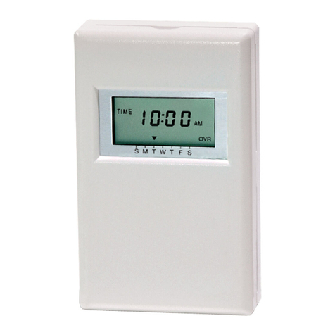
Berker 2948 User manual

1
Zeitschaltuhr-Einsatz
Timer insert
Schakelklok-inzetregelmoduul
Insert de minuterie
Best.Nr. 2948
825 192 01 07.2003
Bedienungsanleitung
Operating Instructions
Bedieningshandleiding
Mode d’emploi

3
2
Funktion
Inhaltsverzeichnis
1. Gefahrenhinweise ............................................................................................... 2
2. Funktion............................................................................................................... 3
3. Installationshinweise ........................................................................................... 4
4. Anschluss ............................................................................................................ 6
5. Technische Daten................................................................................................ 8
6. Gewährleistung ................................................................................................... 9
Inhaltsverzeichnis
D
1. Gefahrenhinweise
Achtung! Einbau und Montage elektrischer Geräte dürfen nur durch eine
Elektrofachkraft erfolgen.
Nicht zum Freischalten geeignet.
Die Zeitschaltuhr wurde für das automatische Schalten von Beleuchtung ent-
wickelt.Falls diese für andere Zwecke eingesetzt wird, welche Gefahren mit sich
bringen könnten (z.B.Schalten von Heizgeräten), so sind vom Anwender diese
GefahrendurchEinsatz zusätzlicher geeigneterSicherheitsmaßnahmen
auszuschließen.
2. Funktion
Der Zeitschaltuhr-Einsatz ist eine System-Komponente und wird in Verbindung
mit dem Zeitschaltuhr-Aufsatz mitTimerfunktion in einer 60 mm Unterputzdose
(Empfehlung:tiefe Dose)montiert.
Das Gerät ermöglicht das programmierte, zeitgesteuerte Schalten verschiedener
Leuchtmittel (siehe technische Daten).Durch den Einsatz eines leistungsstarken
Relais mit potentialfreien Kontakten können Verbraucher bis max.1000 W
geschaltetwerden.
Über zwei separate Nebenstelleneingänge kann derVerbraucher mit einem mecha-
nischenTaster (2-Flächen-Prinzip, 2x Schließer) geschaltet werden.
Der Zeitschaltuhr-Einsatz verfügt über 6 Anschlussklemmen und einen Steck-
verbinder zur Kontaktierung des Aufsatzes.
Zusätzlich kann im Einsatz, beiVerwendung eines Aufsatzes mit Sensoranschluss,
eine 3-polige Klemme (liegt dem Aufsatz bei) positioniert werden.An dieser Klem-
me wird der Dämmerungssensor angeschlossen.
Schnittstelle Aufsatz Sensoranschluss
Potentialfreier KontaktNebenstelle AUS
Nebenstelle EIN Phase
Neutralleiter
OFF
ON
NL
OFF
ON
NL
Datum
Uhrzeit
Mode Set
Prog Zufall Astro
WS
Mo
Di
Mi
Do
Fr
Sa
So
A
B
C
ON OFF
OFF
ON

5
4
Installationshinweise
Installationshinweise
3. Installationshinweise
Wichtig:Die Sensorleitung führt Schutzkleinspannung (SELV). Installations-
vorschriften nachVDE 0100 beachten.
Anschluss Sensor :
UP-Verlegung (Bild A):
Zur UP-Verlegung der Sensorleitung geeignete Leitung wählen.
Empfehlung:Telefonleitung J-Y(ST)Y 2x2x0,6 mm. Die Einzeladern der Sensor-
leitung werden durch einen Isolierschlauch (liegt dem Aufsatz mit Sensoranschluss
bei) geführt.Die Leitung wird dann, zusammen mit dem Isolierschlauch, durch die
Leitungsdurchführung cdes Einsatzes gesteckt und durch den Leitungskanal d
zur Anschlussklemme egeleitet.Der Isolierschlauch muss die Einzeladern von der
äußeren Leitungsisolierung bis zur Anschlussklemme umschließen.Die Anschluss-
klemme (liegt dem Aufsatz mit Sensoranschluss bei) wird, entsprechend der Abbil-
dung, in den Einsatz eingelegt.
AP-Verlegung (Bild B):
Die Sensorleitung cwird hinter der Tragplatte (zwischenWand undTragplatte)
durch die Öffnung ‚ in den Leitungskanal edes Einsatzes eingeleitet.Die Leitung
wird direkt durch den Leitungskanal zur Anschlussklemme fgeführt.Die Leitung
muss präzise im Leitungskanal liegen und darf keine Schlaufen zum 230V An-
schlussklemmraumbilden.
Sensorleitungnach nebenstehendem Schemaanschließen.
Kennzeichnung derLeitungsadern:
Sensor: ‘Masse’= gekennzeichnet
Adapter,Verlängerungsleitung:
‘Dämmerung’=gekennzeichnet
‘Masse’=mittlere Leitung
Der Zeitschaltuhr-Einsatz kann nur inVerbindung mit dem Zeitschaltuhr-Aufsatz mit
Timerfunktionbetrieben werden.
Der Zeitschaltuhr-Einsatz cwird in einer 60 mm Unterputzdose (Empfehlung:tiefe
Dose)montiert.
Die Anschlussklemmen des Einsatzes müssen dabei unten liegen.
Der Aufsatz dwird zusammen mit dem Rahmeneauf den Einsatz aufgesteckt.
Die elektrische Kontaktierung erfolgt über die Stecker fund g.
(Beschreibung, Montage und Anschluss des Aufsatzes siehe separate Anleitung).
A
B

7
6
4.Anschluss Zeitschaltuhr-Einsatz
Phase L mit Eingang Relais verbinden (‘Drahtbrücke’)
Anschluss auf 2 Phasen
Der Zeitschaltuhr Einsatz ist mit potentialfreien Kontakten ausgeführt.
Anschluss
Anschluss
Anschluss mit mechanischer Nebenstelle
Phase L mit Eingang Relais verbinden (‘Drahtbrücke’)

9
8
Gewährleistung
Technische Daten
5.Technische Daten
Nennspannung :AC 230V, 50 Hz (N-Leiter erforderlich)
Schaltleistung
Glühlampen :1000W
HV-Halogenlampen :1000W
NV-Halogenlampenmit
TRONIC-Trafos :750W
Konventionelle Trafos :750 VA
konv.Trafo mind. 85% Nennlast.
Leuchtstofflampen
unkompensiert :500 VA
parallelkompensiert (47µF) :400 VA
Duo-Schaltung :1000VA
Energiesparlampen :Bei Energiesparlampen auf hohe Einschaltspitzen-
strömeachten.
Eignung der Lampen vor dem Einsatz prüfen !
Relaisausgang :1 potentialfreierSchließer
Nicht zum Freischalten geeignet.
Schaltzeitabstand :min.1 Minute
Anschlussklemmen :Schraubklemmen für max.2,5 mm²
oder 2 x 1,5 mm²
Leitungsschutzschalter :max. 16 A
6. Gewährleistung
Wir leisten Gewähr im Rahmen der gesetzlichen Bestimmungen.
Bitte schicken Sie das Gerät portofrei mit einer Fehlerbeschreibung an unsere
zentrale Kundendienststelle:
Berker GmbH & Co. KG
Abt.Service Center
Klagebach 38
D-58579Schalksmühle
Telefon: 0 23 55 / 90 5-0
Telefax: 0 23 55 / 90 5-111

11
10
Function
Contents
1. Warning ............................................................................................................. 10
2. Function............................................................................................................. 11
3. Installation Instructions ..................................................................................... 12
4. Connection ........................................................................................................ 14
5. Specifications .................................................................................................... 16
6. Acceptance of guarantee .................................................................................. 17
Contents
GB
1.Warning
Caution!The installation and assembly of electrical equipment may only be
performed by a skilled electrician.
Not suitable for disconnecting.
This timer has been designed for the automatic switching of lights.If they are used
for any other purposes which may entail hazards (e. g.switching heaters) such
hazards will have to be eliminated by the user by taking additional suitable safety
measures.
2. Function
ThisTimer-insert is a system component to be installed into a 60 mm flush box
(recommendation:deep box) in conjunction with the timer attachment with time
switch function.
The device facilitates the programmed, time-controlled switching of various lighting
fittings (please refer to Specifications).Due to the use of an efficient relay with
potential-free contacts, consumers of up to a maximum of 1000W can be switched.
Via two separate extension inputs, the consumer can be switched by a mechanical
push-button (two-key principle, 2x n.o. contacts).
TheTimer-insert has six connecting terminals and one plug connector for contact
withthe attachment.
In addition, a three-pole terminal (added to the attachment) can be positioned in the
insert.This terminal serves for connecting a twilight sensor.

13
12
Installation Instructions
Installation Instructions
3. Installation Instructions
Important:The sensor line carries protective low voltage (SELV). Please
observe the installation procedures as specified byVDE 0100.
Connecting the Sensor:
BuriedWiring (Figure A):
Choose suitable cable for buried installation of the sensor line.
Recommendation:J-Y(ST)Y 2x2x0.6 mmtelephone cable.Theindividual wiresofthe
sensor line should be put through flexible insulating tubing (added to the attachments
withsensor evaluation).Then,togetherwith the flexibleinsulatingtubing, push theline
through entrance cof the insert and through duct dto terminal e.
The insulating tubing must cover the individual wires from the cable sheath to the
connectingterminal.Put the connectingterminal (added tothe attachmentswith sensor
evaluation) in the insert as shown in the illustration.
SurfaceWiring (Figure B):
Lead sensor line cbehind the supporting plate (between the wall and the
supporting plate) through opening dinto duct eof the insert.The line must be led
directly through the duct to connecting terminal f.The line must be precisely in the
duct and must not form any loops towards the 230 V connecting terminal space.
Connect the sensor line as shown in the opposite illustration.
Wiremarking:
Sensor: ‘Earth’ = marked.
Adapter, extension line:
‘Twilight’= marked.
‘Earth’= middle wire.
TheTimer-insert can only be used in conjunction with the Timer attachment with
time switch function.
Timer-insert cis provided for installation in a 60 mm flush box
(recommendation:deepbox).
The connecting terminals of the insert must be down.
Plug attachment donto the insert together with frame e.
Electrical contacting is established through plug fand g.
(For the description, installation and connection of the attachment, please refer to
separateinstructions.)
A
B

15
14
Connection
Connection
Connection with mechanical extension
Connect phase L with the relay input (‘jumper’).
4.Timer insert Connection
Connect phase L with the relay input (‘jumper’).
Two-phase connection
The timer insert is provided with potential-free contacts.

17
16
Acceptance of guarantee
Specifications
5. Specifications
Ratedvoltage :230V AC, 50 Hz (neutral conductor required)
Switching Capacity
Incandescentlamps :1000 W
Halogen HV lamps :1000W
Halogen LV lamps with
TRONICtransformers :750 W
Convent.transformers :750 VA
Conv.transformer with at least 85 % rated load.
Fluorescentlamps
Uncompensated :500 VA
Shunt-compensated (47µF) :400 VA
Twin-lampcircuit :1000VA
Energy-saving lamps :When using energy-saving lamps,
mind high surge peak currents.
Check lamps for suitability prior to use.
Relay output :1 potential-free n. o. contact
Not suitable for disconnecting.
Switching time interval :1 minute min.
Connectingterminals :Screw terminals for 2.5 mm² max.or 2 x 1.5 mm²
Automaticcut-out :16 A max.
6. Acceptance of guarantee
We accept the guarantee in accordance with the corresponding legal provisions.
Please return the unit postage paid to our central service department giving a
brief description of the fault:
Berker GmbH & Co. KG
Klagebach 38
D-58579Schalksmühle
Germany
Telephone:+49 (0) 23 55 / 90 5-0
Telefax: +49 (0) 23 55 / 90 5-111

19
18
Functie
Inhoudsopgave
1. Veiligheidsinstructies ............................................................................................. 18
2. Functie................................................................................................................... 19
3. Installatie-instructies ............................................................................................. 20
4. Aansluitings ........................................................................................................... 22
5. Technische gegevens............................................................................................ 24
6. Garantie................................................................................................................. 25
NL
Inhoudopgave
1. Veiligheidsinstructies
Attentie! Installatie en montage van elektrische apparaten mogen uitsluitend
door een landelijk erkend elektrotechnisch installateur worden uitgevoerd.
Niet geschikt voor spanningvrij schakelen.
De schakelklok is voor het automatisch schakelen van verlichtingen ontworpen.
Indien de schakelklok voor andere toepassingen wordt gebruikt, die gevaar kunnen
opleveren (b.v.schakelen van verwarmings-apparatuur), dient de gebruiker
dergelijke gevaren via geschikte veiligheidsmaatregelen uit te bannen.
2. Functie
Het schakelklok-inzetmoduul is een systeemcomponent en wordt in combinatie met
het schakelklok-opzetmoduul met timerfunctie in een verzonken 60 mm wanddoos
(advies:diepe doos) gemonteerd.
Het toestel maakt geprogrammeerd, tijdgestuurd schakelen van verschillende typen
verlichting(zie technische gegevens) mogelijk.Doortoepassingvaneenkrachtigrelais
metpotentiaalvrije contacten kunnenverbruikers totmax.1000W worden geschakeld.
Via twee afzonderlijke extensie-ingangen kan de verbruiker met behulp van een me-
chanische schakelaar (2-standen-schakeling, 2x sluitcontact) worden geschakeld.
Het schakelklok-inzetmoduul heeft 6 aansluitklemmen en een steekconnector voor
contactering vanhet opzet-moduul.
Tevenskanophet schakelklok-inzetmoduul een3-polige klem (leveringspakketdisplay-
moduul) worden geplaatst.Op deze klem wordt de schemersensor aangesloten.
Table of contents
Languages:
Other Berker Timer manuals