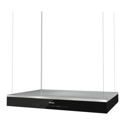
Beko CCB 7140 XA User manual

Hood
User Manual
CCB 7140 XA

Please read this user manual first!
Dear Customer,
Thank you for prefering a Beko product. We hope that you get the best results from your product
which has been manufactured with high quality and state-of-the-art technology. Therefore, please
read this entire user manual and all other accompanying documents carefully before using the product
and keep it as a reference for future use. If you handover the product to someone else, give the user
manual as well. Follow all warnings and information in the user manual.
Remember that this user manual is also applicable for several other models. Differences between
models will be identified in the manual.
Explanation of symbols
Throughout this user manual the following symbols are used:
CImportant information or useful hints
about usage.
AWarning for hazardous situations with
regard to life and property.
BWarning for electric shock.
Packaging materials of the product are
manufactured from recyclable materials
in accordance with our National
Environment Regulations.
Do not dispose of the packaging materials together with the domestic or other wastes. Take them to
the packaging material collection points designated by the local authorities.
This product was manufactured using the latest technology in environmentally friendly conditions.

3 / 11 ENHood / User Manual
1 Recommendations and Suggestions 4
1.1 Installation . . . . . . . . . . . . . . . . . . . . . . . . . .4
1.2 Use . . . . . . . . . . . . . . . . . . . . . . . . . . . . . . .4
1.3 Maintenance . . . . . . . . . . . . . . . . . . . . . . . .5
2 Characteristics 6
2.1 Components. . . . . . . . . . . . . . . . . . . . . . . . .6
2.2 Dimensions . . . . . . . . . . . . . . . . . . . . . . . . .6
2.3 Technical Specifications . . . . . . . . . . . . . . . .6
3 Installation 7
3.1 Drilling the Support surface and Fitting the
Hood . . . . . . . . . . . . . . . . . . . . . . . . . . . . . .7
3.2 Connection. . . . . . . . . . . . . . . . . . . . . . . . . .7
3.2.1 Ducted Version Air Exhaust System . . . . . .7
3.2.2 Recirculation Version Air Outlet. . . . . . . . . .8
3.2.3 Electrical Connection . . . . . . . . . . . . . . . . .8
4 Use 9
4.1 Control panel . . . . . . . . . . . . . . . . . . . . . . . .9
5 Maintenance 10
5.1 Grease Filters. . . . . . . . . . . . . . . . . . . . . . .10
5.1.1 Cleaning Metal Self- Supporting Grease
Filters . . . . . . . . . . . . . . . . . . . . . . . . . . .10
5.1.2 Cleaning Multilayer Metal Grease Filters . .10
5.1.3 Replacing Synthetic Grease Filter . . . . . . .10
5.2 Odour filters (Recirculation version) . . . . . .11
5.2.1 Replacing Activated Charcoal Filters . . . . .11
5.3 Lighting . . . . . . . . . . . . . . . . . . . . . . . . . . .11
5.3.1 Light Replacement. . . . . . . . . . . . . . . . . .11
TABLE OF CONTENTS

4 / 11 EN Hood / User Manual
1 Recommendations and Suggestions
A
The Instructions for Use apply to
several versions of this appliance.
Accordingly, you may find descripti-
ons of individual features that do not
apply to your specific appliance.
1.1 Installation
• The manufacturer will not be held liable for any
damages resulting from incorrect or improper
installation.
• The minimum safety distance between the cook-
er top and the extractor hood is 650 mm (some
models can be installed at a lower height, please
refer to the paragraphs on working dimensions
and installation).
• Check that the mains voltage corresponds to
that indicated on the rating plate fixed to the in-
side of the hood.
• For Class I appliances, check that the domestic
power supply guarantees adequate earthing.
• Connect the extractor to the exhaust flue through
a pipe of minimum diameter 120 mm. The route
of the flue must be as short as possible.
• Do not connect the extractor hood to exhaust
ducts carrying combustion fumes (boilers, fire-
places, etc.).
• If the extractor is used in conjunction with non-
electrical appliances (e.g. gas burning appli-
ances), a sufficient degree of aeration must be
guaranteed in the room in order to prevent the
backflow of exhaust gas. The kitchen must have
an opening communicating directly with the
open air in order to guarantee the entry of clean
air.
• There shall be adequate ventilation of the room
when the range hood is used at the same time
as appliances burning gas or other fuels. (Not
applicable to appliances that only discharge the
air back into the room)
• There is a risk of fire if cleaning is not carried out
in accordance with the instructions.
• Do not flambé under the range hood.
• Caution: Accessible parts may become hot when
used with a cooking appliance.
• The appliance is not intended for use by persons
(including children) with reduced physical, sen-
sory or mental capabilities, or lack of experience
and knowledge, unless they have been given su-
pervised or instruction concerning use of the ap-
pliance by a responsible person for their safely.
• Young children should be supervised to ensure
that they do not play with the appliance.
• If the supply cord is damaged, it must be re-
placed by the manufacturer or its service agent
or a similarly qualified person in order to avoid
a hazard.
The instructions must include details concerning
cleaning instructions and frequency of cleaning
1.2 Use
The extractor hood has been designed exclusively
for domestic use to eliminate kitchen smells.
• Never use the hood for purposes other than for
which it has been designed.
• Never leave high naked flames under the hood
when it is in operation.
• Adjust the flame intensity to direct it onto the
bottom of the pan only, making sure that it does
not engulf the sides.
• Deep fat fryers must be continuously monitored
during use: overheated oil can burst into flames.
• The hood should not be used by children or per-
sons not instructed in its correct use.

5 / 11 ENHood / User Manual
1 Recommendations and Suggestions
1.3 Maintenance
• The exhaust air must not be discharged into a
flue which is used for exhausting fumes from
other appliances burning gas or other fuels. (Not
applicable for appliances which only discharge
air back into the room)
• The minimum distance between the support-
ing surface for the cooking vessels on the
hob and the lowest part of the range hood:
When the range hood is located above a gas ap-
pliance, this distance shall be 65cm. If the in-
structions for installation for the gas hob specify
a greater distance, this must be taken into ac-
count. (The distance of 65cm can be reduced
for non combustible parts of range hoods and
parts operating at safety extra low voltage pro-
vided these parts do not give access to live parts.
Distance may be reduced to 60cm to align with
the AGA code.
• Regulations concerning the discharge of air have
to be fulfilled
• Warning: Failure to install the screws or fixing
device in accordance with the instructions may
result in electrical hazards.
• Switch off or unplug the appliance from the
mains supply before carrying out any mainte-
nance work.
• Clean and/or replace the Filters after the speci-
fied time period (Fire hazard).
• Clean the hood using a damp cloth and a neutral
liquid detergent.

6 / 11 EN Hood / User Manual
2.1 Components
Ref. Q.ty Product Components
1 1 Hood Body, complete with: Controls,
Light, Blower, Filters
8 1 Directional Air Outlet grille
9 1 Reducer Flange ø 150-120 mm
Ref. Q.ty Installation Components
12e 2 Screws 2,9 x 9,5
Q.ty Documentation
1 Instruction Manual
2.2 Dimensions
2 Characteristics
Width 702 mm
Depth 305 mm
Height 284 mm
Supply voltage 220 - 240 V, 50-60 Hz
Control 3 positions
Suction power 580 m3/h
Motor power 205 W
Lamp power 2X28 W
Total power 261 W
Air outlet pipe
diameter 120 mm
Net weight 6,6 kg
Gross weight 9,3 kg
2.3 Technical Specifications
Markings on the product or the values stated in other documents
supplied with the product are values obtained under laboratory
conditions as per relevant standards. These values may vary according
to the usage of the product and ambient conditions.
Hood Type 52 70
L1 522 702

7 / 11 ENHood / User Manual
3.1 Drilling the Support surface and
Fitting the Hood
Hood Type 52 70
L1 497 677
Make a rectangular opening on the base of the
hanging unit, leaving a minimum of 13 mm from
the outer edges.
Snap-On Fitting
For hoods with snap-on side supports only, set
up for a support panel thickness of between 15
mmand 30 mm.
• Insert the hood until the side supports snap into
place.
• Lock in position by tightening the screws Vf
from underneath the hood.
3 Installation
Screw Fitting
For hoods without snap-on side supports only.
• Fix the hood to the hanging unit using the
screws 12f (3.5x16 self-threading) provided.
3.2 Connection
3.2.1 Ducted Version Air Exhaust
System
When installing the ducted version, connect the
hood to the chimney using either a flexible or rigid
pipe ø 120 or 150 mm, the choice of which is left
to the installer.
• To install a ø 120 mm air exhaust connection
insert the reducer flange 9 on the hood body
outlet.
• Fix the pipe in position using sufficient pipe
clamps (not supplied).
• Remove any activated charcoal filters.

8 / 11 EN Hood / User Manual
3.2.2 Recirculation Version Air Outlet
• Cut a hole ø 125 mm in the wall unit over the
hood.
• Insert the reducer flange 9 on the hood body
outlet.
• Connect the hood body outlet to the top part of
the wall unit using a rigid or flexible pipe ø120
mm, to be selected by the installer.
• Fix the pipe in position using sufficient pipe
clamps (not supplied).
• Fix the directional grille 8 on the recirculation
air outlet using the 2 screws 12e (2,9 x 9,5)
provided.
• Ensure that the activated charcoal filters have
been inserted.
3.2.3 Electrical Connection
• Connect the hood to the mains through a two-
pole switch having a contact gap of at least 3
mm.
• When opening the sliding carriage for the first
time after installing the hood, pull it out briskly
until it clicks.
3 Installation

9 / 11 ENHood / User Manual
4 Use
4.1 Control panel
L Light Switches the lighting system on and off
M Motor Switches the extractor motor on and off
V Speed Sets the operating speed of the extractor:
1. Low speed, used for a continuous and silent air change in the presence
of light cooking vapour.
2. Medium speed, suitable for most operating conditions given the optimum
treated air flow/noise level ratio.
3. Maximum speed, used for eliminating the highest cooking vapour emis-
sion, including long periods

10 / 11 EN Hood / User Manual
5 Maintenance
5.1 Grease Filters
5.1.1Cleaning Metal Self- Supporting
Grease Filters
• The filters must be cleaned every 2 months of
operation, or more frequently for particularly
heavy usage, and can be washed in a dishwas-
her.
• Remove the filters one at a time by pushing
them towards the back of the group and pulling
down at the same time.
• Wash the filters, taking care not to bend them.
Allow them to dry before refitting.
• When refitting the filters, make sure that the
handle is visible on the outside.
5.1.2 Cleaning Multilayer Metal
Grease Filters
• The filters must be cleaned every two months of
operation, or more frequently with heavy usage
and can be washed in a dishwasher.
• Release the filter retaining grill using the lateral
sliding handles.
• Remove the filter retaining clips.
• Remove and wash the filters. Allow them to dry
before refitting.
• Replace the filters on the grill, fix them in posi-
tion using the filter retaining clips and close the
filter retaining grill.
5.1.3 Replacing Synthetic Grease
Filter
• The filter is not washable and cannot be rege-
nerated, and must be replaced approximately
every two months of use, or more frequently
with heavy usage.
• Release the filter holder frame using the lateral
sliding handles.
• Remove the fIlter retaining clips.
• Replace the saturated synthetic filter.
• Fix the new synthetic filter using the retaining
clips and close the filter holder frame.
Table of contents
Other Beko Ventilation Hood manuals

Beko
Beko HCA62320W User manual

Beko
Beko CTB 6407 W User manual

Beko
Beko CWB 7441 X User manual

Beko
Beko CWB 9910 B User manual

Beko
Beko BHCA66741BBHF User manual

Beko
Beko HCA62320B User manual

Beko
Beko CFB 6310 W User manual

Beko
Beko 01M-8848063200-2223-10 User manual

Beko
Beko CFB 6432 XGA User manual

Beko
Beko HCA62320W User manual

Beko
Beko HCA 63420 B User manual

Beko
Beko CFB 6433 XH User manual

Beko
Beko HCB91731BX User manual

Beko
Beko CFB 6463 X User manual

Beko
Beko BCL 90X User manual

Beko
Beko CTB 6407 W User manual

Beko
Beko HCA92844BH User manual

Beko
Beko BHCA63741BHSI User manual

Beko
Beko HNT61630X User manual

Beko
Beko CTB 6407 W User manual