Beko Drypoint ACC 4 User manual

EN
Instruction & Technical Manual
4 - 35
BEKO TECHNOLOGIES CORP. 900 Great SW Parkway, Atlanta, Georgia 30336, USA

The product to which this manual refers must not be supplied, installed,
used, operated or serviced until the contents of the manual has been
fully read and understood by all relevant personnel.
Please complete the following information at the time of installation
found on the rating label on the upper right hand side of dryer
Model Number
Serial Number
Regulated Inlet Pressure
Filtration present with Dryer
Outlet Flow of Dryer
Compressor Outlet Flow
Supply Voltage
When contacting the manufacturer regarding this product, please have
the above stated information at hand to speed up your query.

1Safety 4
Safety Guidelines 4
Symbols 5
2General Description 6
Function of the Dryer 6
Package Contents 7
3Mechanical Installation 9
4Electrical Installation 15
5Operation 18
Start-Up 18
Shut Down 19
6Maintenance 25
Servicing 25
Purge Plug 28
Exhaust 29
Replacing Shuttle Valves 31
7Energy Management 32
8Troubleshooting 38
9Technical Data 42
10 Component Parts 44
11 Spares Information 47
12 Warranty 49
Contents

4Heatless Desiccant Dryers |Instruction Manual
The following safety guidelines must be
strictly observed.
• Leave this manual at the place of installation of
the product.
• It is essential that only the manufacturer or its appointed
agents carry out maintenance and servicing work.
Users, maintenance and servicing personnel must be familiar
with:
• Accident prevention regulations.
• Safety information (general and specic to the unit).
• Safety devices of the unit.
• Measures to be taken in case of an emergency.
• Allow only suitably trained persons to be involved with
installation, start-up, operation, servicing and maintenance
of the product.
• It is the responsibility of the installer to ensure that the
pipe work to and from the dryer is suitable, in accordance
with applicable legislation and subject to inspection and
testing prior to being put into service. All piping must be
adequately supported.
• Before carrying out any maintenance or servicing work the
unit must be taken out of operation. Users and others will
be exposed to risk if work is carried out while the unit is
running. This means electrical disconnection plus isolation
from the compressed air supply and full depressurization.
• Only trained and competent persons familiar with the
electrical requirements of the unit as laid out in this
manual and electrical safety rules and regulations should
be allowed to carry out work on the electrical components
and power supply to the unit.
• When carrying out any work on the unit, use only
correctly sized appropriate tools in good condition.
• Only use original spare parts and accessories from the
manufacturer. There is no guarantee that non-original
parts have been designed and manufactured to meet
the safety and operational requirements of the unit. The
manufacturer assumes no liability for any equipment
malfunction resulting from the use of non-approved parts.
Safety
• If carrying out installation work above head height, use
suitable and safe working platforms or other means of
working access.
• Do not make any constructional changes to the product.
Any changes or modications may only be carried out by
the manufacturer.
• Any faults or defects that could affect safety must be put
right fully before using the unit.
• Used items and materials must be disposed of in the
correct manner, complying with local laws and regulations,
in particular the desiccant cartridge.
Section 1: Safety

5
Heatless Desiccant Dryers | Instruction Manual
Risk of Danger
Risk of High Pressure
Equipment Protected by
Double Insulation
Risk of Electric Shock
Warning
Important Note
Section 1: Safety
Figure 1.1: Denition of symbols
Manual Handling
As with all areas of the workplace, Health and Safety is of
great importance and must be given due care and attention.
While working with this equipment, manual handling
regulations must be considered and adhered to.
Full advice, support and guidance should be detailed in your
Health and Safety Policy and Manual Handling guide, please
take the time to familiarize yourself with these documents.
The Manual Handling Operations Regulations apply to a wide
range of manual handling activities, including lifting, lowering,
pushing, pulling or carrying.
We ask every person handling this product to take the
responsibility for their own Health and Safety and the Health
and Safety of others around them. If you feel there is a
signicant risk, you must take steps to either remove the risk
altogether, or reduce the risk prior to carrying out the activity.
If you need further support or guidance with this, please
consult your line manager or the HR Department.
There are safe systems of work and correct procedures in
relation to manual handling, please consult these documents
available within the workplace.
We ask everyone handling this product to:
• Follow appropriate systems of work laid down
for their safety.
• Make proper use of any equipment provided for
their safety.
• Inform the company if they identify hazardous
handling activities.
• Take care to ensure that their activities do not put
others at risk.
If in doubt, please seek further advice and ensure you always
follow the correct procedures and guidance.
For more information please see our Health and Safety
manual attached.
When used in the UK, a 3 amp fuse should be tted as per the
wiring diagram (gure 4.4).

6Heatless Desiccant Dryers |Instruction Manual
Function of the Dryer
The dryer is designed to provide a smooth, controlled and
uninterrupted delivery of dry compressed air. Wet air passes
through a pre-lter and travels down to the bottom valve
assembly. The air is then fed through the bottom of the
desiccant bed and moves through the high performance
desiccant until it becomes dry. On exit from the desiccant
cartridge, the air is passed through the outlet valve assembly.
During this process, the dryer control system cycles the process
air between the two desiccant towers. While one chamber is
on stream removing water vapor, the other is being carefully
depressurized in preparation for regeneration. The desiccant
bed is regenerated by expanding a small amount of dry
process air, or purge air, through the saturated desiccant.
Purge air passes to atmosphere through the silencer, which is
tted to an exhaust valve. The chamber is then repressurized,
with the control system assuring each chamber is at full
operational pressure prior to changeover.
This ensures a reliable and efcient operation. The air stream is
switched and the cycle repeats on a continuous basis.
General Description
Section 2: General Description
This manual is valid for the following dryer models
ACC 4 ACC 6 ACC 8
ACC 10 ACC 15 ACC 25
ACC 35

7
Heatless Desiccant Dryers | Instruction Manual
Package Contents
The dryer is delivered in protective packaging. Take care when transporting, loading and unloading the unit.
The package contains the following items (refer to gure 2.1):
Figure 2.1: Package contents
INSTRUCTION MANUAL
TUBING
CLEARPOINT FILTER
DIN PLUG
BEKOMAT (OPTIONAL)
M & M UNION
CERTIFICATE OF CONFORMITY
CONNECTION KIT (OPTIONAL)
041705 001 01 Ra
6789
6789
6789
6789
6789
6
789
678
9
6
7
89
67
8
9
DRYPOINT ACC DRYER
Section 2: General Description

8Heatless Desiccant Dryers |Instruction Manual
Figure 2.2: Models 4 SCFM – 35 SCFM
Section 2: General Description
13
12
5
11
15
16
9
10
1
21
14
22
20
8
3
67
5
4
19
18
17
2
1. Top valve assembly
2. Control unit
3. Bottom valve assembly
4. Dryer base
5. Bottom valve xing bolt
6. Front panel
7. Front panel xing screw
8. Pressure housing
9. Pressure housing retaining bolt
10. Desiccant cartridge (comes with dust lter)
11. Multiport manifold
12. Top cover
13. Top cover xing screw
14. Rear panel
15. Banjo xing bolt
16. Pressure seal
17. Exhaust silencer
18. Purge plug
19. Purge plug xing screw
20. Pre-lter
21. Power cord
22. Down tube

9
Heatless Desiccant Dryers | Instruction Manual
Connecting the pre-lter to the dryer
• 4 SCFM – 35 SCFM, Utilize O-ring and bolts supplied to
assemble lter as per gure 3.1.
• Fit 5/32” (4mm) tubing to lter and dryer’s built-in drain
valve inlet.
• Pipe away condensate with 5/32” (4mm) tubing from the
dryer’s drain outlet. Ensure condensate is drained into an
oil/water separator.
• Fit any further ltration or ancillary equipment.
• Drain kits supplied with dryer and comprise of the
following: Swivel elbow adapter and 5/32” (4mm) tubing.
It is recommended that a bypass line including lter is
installed, as per gure 3.13
17. Exhaust silencer
18. Purge plug
19. Purge plug xing screw
20. Pre-lter
21. Power cord
22. Down tube
1
2
Figure 3.1: Connecting pre-lter
Mechanical Installation
Section 3: Mechanical Installation
1. Inlet
2. Outlet
Figure 3.2: Connecting lter drain
All tubing should be secured up to the point of drain to
prevent whipping during discharge.
10 Heatless Desiccant Dryers |Instruction Manual
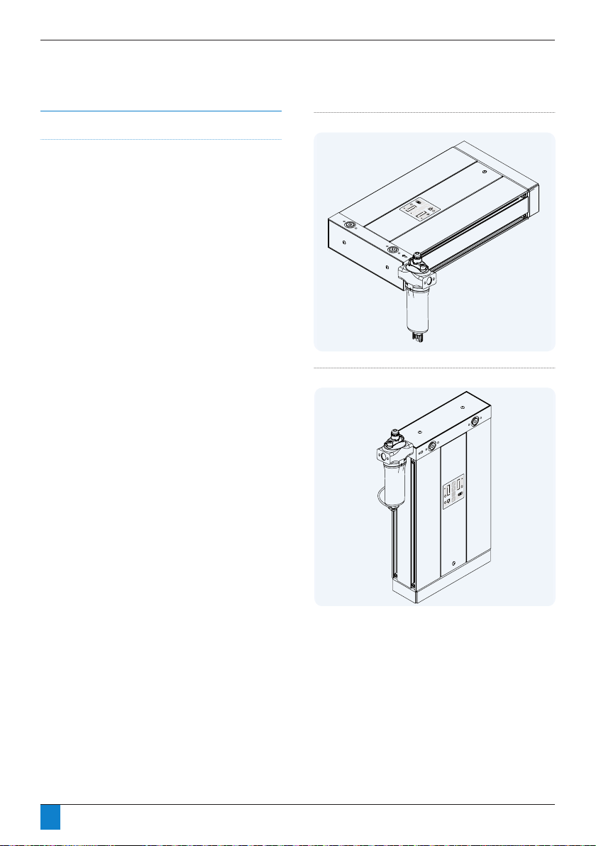
Orientation
The dryers are designed to operate in both vertical and
horizontal orientation.
Figure 3.3: Horizontal orientation
Figure 3.4: Vertical orientation
Section 3: Mechanical Installation
This manual suits for next models
6
Table of contents
Other Beko Dehumidifier manuals


