BeingHD VPX-500 User manual
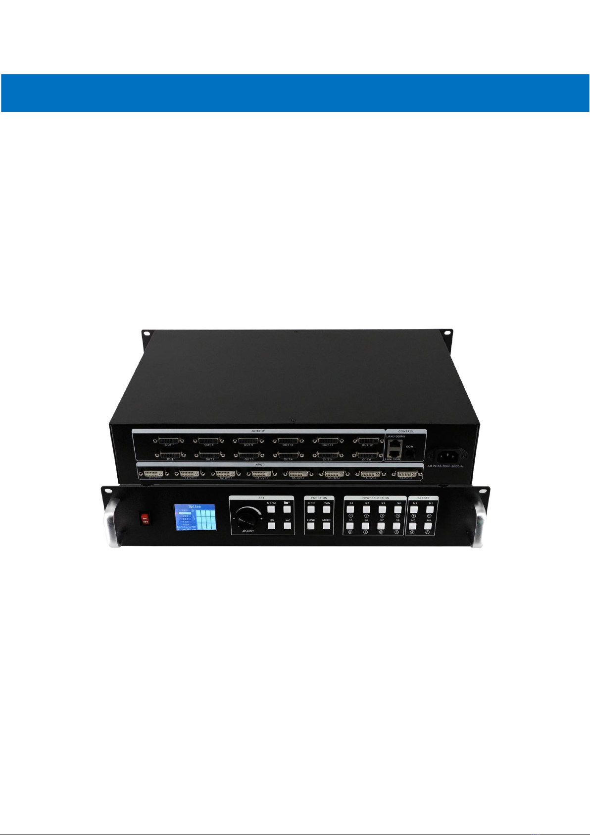
Video Wall Processor
8 DVI-I inputs and 12 DVI outputs Video Wall controller with Preview function
Version number: V1.01.01
User Manual

1
1. Introduction
This video wall processor is a high-end video processing equipment developed and manufactured
by our company for LCD large screen display and so on. It has adopted the CrossInt smart splicing
technology specially designed for splicing display and all display modules are locked by FST
technology before synchronous output, eliminating the asynchronous display between contents
of multiple modules.
2. Features
Supports 8 DVI-I inputs Compatible with DVI/HDMI/VGA/CVBS).
Up to 8 layouts/windows in total
Colorful LCD screen for the real-time information and menu setting
Supports sources real-time preview function(with 1000M LAN port)
All 60Hz image processing, achieving smooth and non-tearing images
Support output port mapping, allowing blind wire connections
Support black/blue screen while wrong sources output
Support mode and source switching effects(CUT of FADE effects)
2.Hardware Introduction
2.1 Front Panel
1POWER: Power switch ON/OFF
2Colorful LCD screen: for fast setting, information look up
3SET: including ADJUST knob, OK, MENU, BACK and CONFIRM
4FUNCTION: Function key area which includes INFO, WIN, FUNC, MODE
5INPUT SELECTION: 8 signal sources fast switching buttons
6PRESET: User-Mode recall buttons
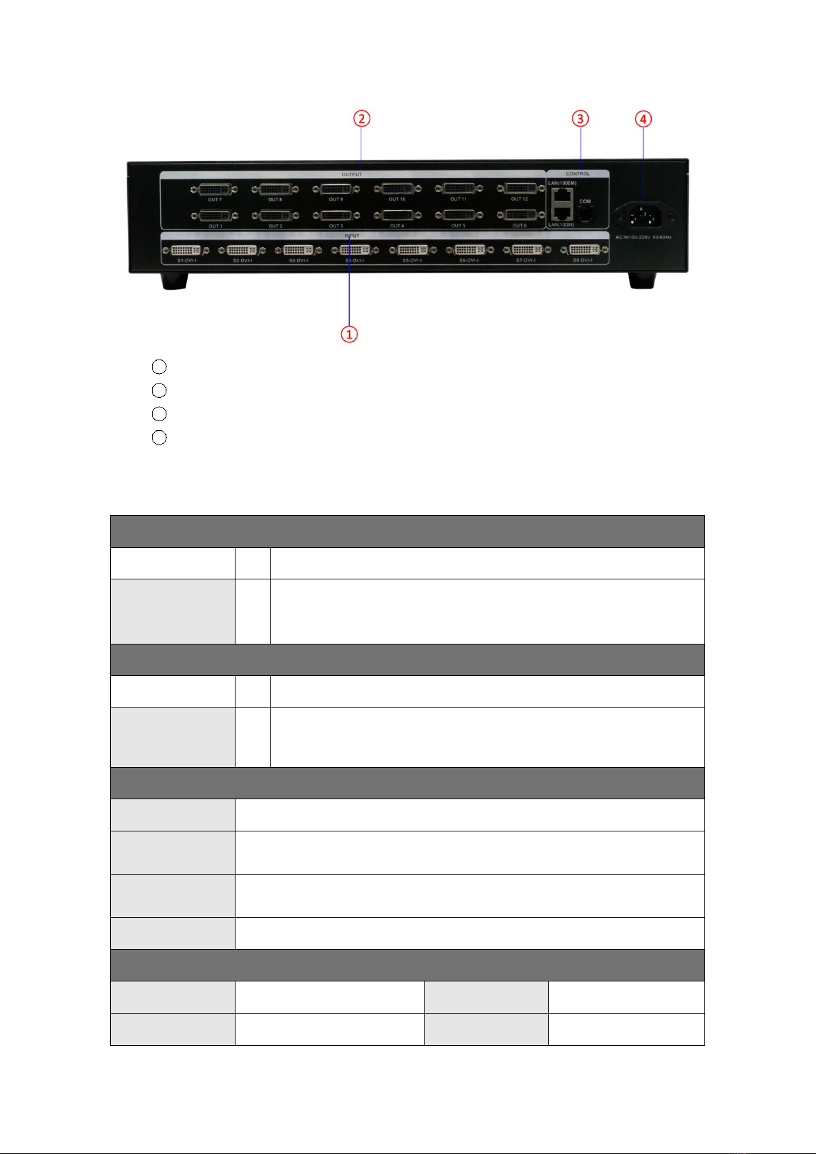
2.2 Back panel
2
1INPUT: 8 DVI-I input ports (Compatible with DVI/HDMI/VGA/CVBS)
22OUTPUT: 12*DVI output ports
3CTRL: Control port which contains LAN (100M), LAN (1000M), COM (serial port)
4POWER: Power supply port, AC 110-220V 50/60Hz
3. Specification
Video Inputs
Type
Qty
Description
DVI-U
8
Support up to 1920×1200@60Hz, downward compatibility.
Support DVI/HDMI/VGA/CVBS with different connectors
Compatible with HDMI1.3 and lower version, EDID version 1.3
Video Outputs
Type
Qty
Description
DVI-D (24+1)
12
Resolutions: 1024×768@60Hz till 1920×1080@60Hz
Support 60Hz/50Hz/30Hz output frame rates
Function Description
Outputs
12 outputs support splicing mode of arbitrary form, such as: 3×4, 2×6 etc.
8 layouts/windows
Up to 8 windows or layouts in total
Each layout can be freely zoomed and adjusted. Images can overlap each other.
1000M Preview
The signal image can be gained on computer at real time by control software
which includes both input signal and output signal
Switching Effect
When switching signals or user-modes, users can set up different effects and time
Others
PC Control
RS232/RJ45 Ethernet
Dimension
440x290x90mm
Weight
5.4kg
Input Power
100-220V 60/60Hz

3
Work Environment
Temp: 0-40℃; Humid: 0-95%
Warranty
2 years
4. Device Debugging
4.1 Device Connection
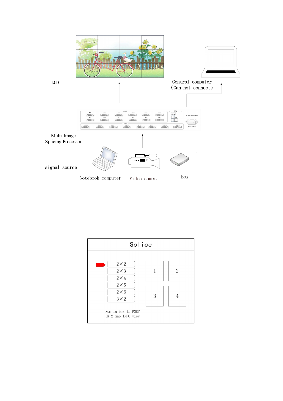
Device connection could be divided into three parts: power connection, signal connection
and control connection (used for software debugging).
Power connection: device power supply. Connection method: connect power cord to power
plug.
Signal connection: the method transferring signal from signal source to LED large screen,
method: signal source (e.g.: computer)→Mosaic Processor →LCD.
Control connection: connect control computer with device control port and debug device
connection method. There are three connection methods
(1) Connect 100MB network control port with splicer LAN(100M) port, which can set device
software
(2) Connect computer gigabit network port with splicer LAN(1000M) port, which can not
only set device but also echo signal source image.
(3) Connect one crystal head of serial port line which is randomly donated by device with
splicer COM port, and plug DB9 into computer serial port. Any kind of method among the
three can realize device software control.
Connection diagram:
4
4.2 Debugging Steps
Step 1: Press “MENU”to enter into main menu interface and click “Splicing Mode”to select
splicing mode: 2×2、2×3、2×4、2×5、2×6、3×2、3×3、3×4、4×2、4×3、5×2、
M×N.
Note: Select M * N to customize the stitching method
Step 2: To get back to main menu interface to select “Image layout”and enter into image
number selecting interface to select image number required to be set.

5
Note: This step can be skipped for signal image. For multi-image, it’s OK if image number and item
requirement are in consistent. Following operations can be taken to set when layout are not in consistent.
Step 3: Press “OK”and return to main menu interface; select “Image parameter”and enter into
its setting interface to set size and position of each image.
Note: there are two ways for number input:
(1) Adjust by rotate knob. Step length can be adjusted by “×1” “×10”“×100”, for instance, “×100”means that
number of rotate knob increases by 100 each time.
(2) Input by number of the front panel. For example, of the key refers to figure 1.
Step 4: Press “MENU”and return to main menu interface; select “Save setting”to enter into Data
storage interface; select any mode and click “OK”to save data.

6
Note: Mode 1 is default startup data of device boot; it’s suggested that the most common mode or that
required by device boot should be saved to Mode 1.
At this point, basic device debugging is completed. If there is other requirement, repeat the
operation and save it as other mode.
After device debugging, just recall saved data according to different condition requirements in
later stage.
Data recall is divided into forms:
(1) For Shortcut key call, only select and press the “M1-M4”buttons on the front panel which
is convenient when mode scenario is few.
(2) For users to recall from the Main Menu, press “MENU”and select “User Mode”to enter
into its extraction interface. Then select needed mode and click “OK”.
4.3 Case Study
Device debugging steps are explained by following cases.
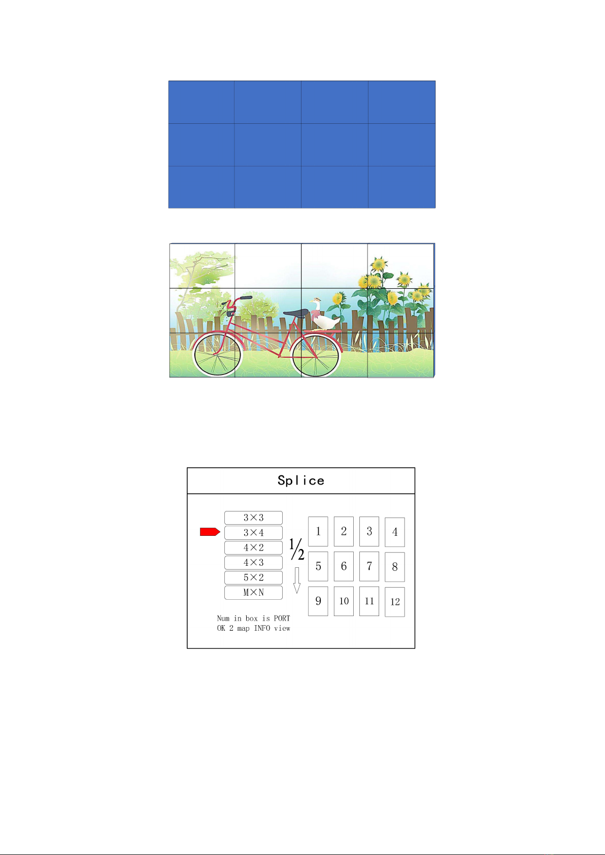
Case: There are 12 LCD screens arranged in 3 rows and 4 columns, as shown in the following figure:
Requirement: all LCD screens are spliced together as a whole one :
7
Arrangement of LCD screen
Display chart
Debugging Steps:
Step 1: Press “MENU”and enter into main menu interface to select “Cross Mosaic”of the first
item “Device mode”.
Step 2: Press “OK”to return to main menu interface; The large screen splicing is finished,
select signal source needed to display on screen and click corresponding key(s1-s8).
Step 3: After normal display of large screen, save all setting data. Press“Save setting”to enter
into “Save setting”interface to select “Mode 1”and click “OK”. Things will be fine when it
suggests saving successfully.

8
Note: Mode 1 is default startup data of device boot; it’s suggested that the most common mode should be
saved to Mode 1 and the device can save 32 kinds of modes at most.
4.4 Function key:
Brief explanation of function key:
INFO: Information query key. Click this key and enter into its interface showing whether all
signal sources are inputting normally. Its interface is shown as below. Red light means signal is
lost while green one shows signal is normal.
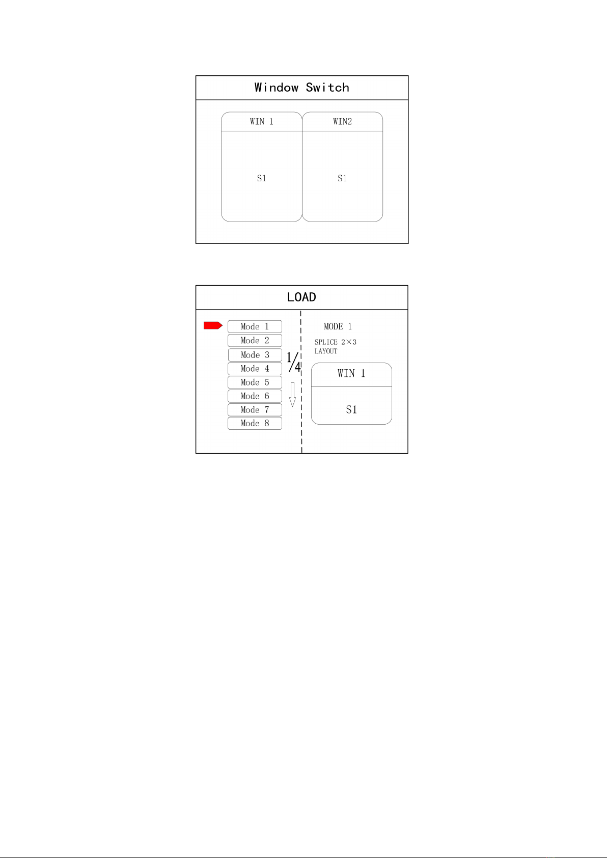
WIN: Image key. Click this key to enter into its interface and signal source selection can be
made in following interface.
9
MODE: Mode recall key…Press this button to enter the user mode interface, and users can
recall the saved modes
FUNC: Function key. Press this key to enter into its interface which includes: brightness
adjustment, special effect switch, VGA adjustment, image matting setting, edge feather,
transparency setting, intelligent warm backup, preview monitor, IP setting, serial port, freeze
frame, local and global, color space, input brightness and switch time. The following are
explanations of those common functions.
1. Brightness adjustment
The device supports 1-255 stairs brightness adjustment. Brightness of all screen body can
be adjusted synchronously to meet customers’different brightness adjustment
requirements for different conditions.
2. Output condition
Use this button to set black screen or blue screen, and then you can switch the output
state.
3. Special effect switch
The device supports directly switching the fade-in and fade-out effect, and ensures that
the switching process is without flower screen, flash screen or black screen.
4. Special effect time
Set image switch times or switch time among different modes with the range of 0.2s-3s.
5. VGA adjustment
Table of contents


