beier USM-RC-2 User manual

D Sound module USM-RC-2
03.02.2014
BEIER-Electronic 1
Operating Manual
Sound module
USM-RC-2
V1.12
BEIER-Electronic
Winterbacher Str. 52/4, 73614 Schorndorf - Weiler
Telefon 07181/46232, Telefax 07181/45732
Internet: http://www.beier-electronic.de/modellbau

D Sound module USM-RC-2
2
BEIER-Electronic 03.02.2014
Table of Contents
Table of Contents ....................................................................................................... 2
Introduction................................................................................................................. 4
Safety notes................................................................................................................ 5
Technical Data............................................................................................................ 6
Operating Modes: Digital, analogue and mix mode .................................................... 7
Pin assignments in digital mode ................................................................................. 8
Wiring diagram for digital mode .................................................................................. 9
Pin assignment in analogue mode............................................................................ 10
Wiring diagram for analogue mode........................................................................... 11
Pin assignment in mix mode..................................................................................... 12
Wiring diagram for mix mode.................................................................................... 13
Installation of the sound module ............................................................................... 14
Connection of the sound module .............................................................................. 14
Connection of the sound module in digital mode ...................................................... 18
Connection of the sound module in analogue mode................................................. 20
Connection of the sound module in mix mode.......................................................... 21
Loudspeaker............................................................................................................. 22
Volume control.......................................................................................................... 23
Sounds ..................................................................................................................... 24
Engine sound............................................................................................................ 25
Turning on/off engine sound ..................................................................................... 28
Adjusting the engine sound to the driving speed ...................................................... 29
Functions of the sound module................................................................................. 30
Additional sounds 1 - 30 ........................................................................................... 31
Random sounds ....................................................................................................... 33
WAV-Player .............................................................................................................. 33
Functional assignment at proportional channels #1 - #4 .......................................... 35
Stick simulation via keys or switches........................................................................ 37
One-channel multi-function selection (EKMFA) ........................................................ 38
Nautic mode / Multiswitch mode ............................................................................... 39
Switching-outputs ..................................................................................................... 41
Output sequences .................................................................................................... 47
Servo outputs ........................................................................................................... 48
Voltage monitoring.................................................................................................... 49

D Sound module USM-RC-2
03.02.2014 BEIER-Electronic 3
Current monitoring.................................................................................................... 49

LEDs on the sound module ...................................................................................... 51
PC-Software „USM-RC-2 Sound-Teacher“............................................................... 52
Using the software “USM-RC-2 Sound-Teacher“ ..................................................... 54
Saving sounds and configurations on SD card ......................................................... 76
Transferring the configurations with the data cable K-USB-2 ................................... 76
Adjustments of the driving sound with the driving sound diagram ............................ 77
Sound simulation ...................................................................................................... 80
Testing functions on the sound module with help of the data cable K-USB-2........... 80
Diagnosis.................................................................................................................. 81
Firmware update....................................................................................................... 84

D Sound module USM-RC-2
4
BEIER-Electronic 03.02.2014
Introduction
The sound module USM-RC-2 was developed for the RC model construction in order
to equip models, with an as realistic as possible, speed-dependent (e.g. engine
sound). Additional turn on-, turn off-, starting-, stopping-, idling-, braking- and driving
backward sounds can be played, too. To make the backround noise perfect, in
addition to the engine sound, up to 30 additional sounds can be played. In addition 8
easy configurable random sounds are possible as well.
The driving speed of the model, is either been taken from 1 or 2 motors (analogue-
and mix mode), or 1 or 2 proportional channels (digital mode) of the receiver are
used for the speed information.
The sounds are stored on a micro-SD-card and can be changed at any time. For this
purpose, just a Windows PC with SD-cardreader and our software "USM-RC-2
Sound-Teacher" is needed. Therefore you can use this sound module for a variety of
models and can customize it to your own imaginations.
There is already a powerful double amplifier (2x20W) onboard, so you only need to
connect 1 or 2 speakers for the sound playback. An additional amplifier is no more
needed.
In addition there are up to 12 switching outputs for the connection of LEDs, lamps,
relays for example. Furthermore different light effects (light, stop light, indicators,
hazard warning light, MG fire, flickering-light and so forth) can be implemented at
these outputs.
Any number of switching outputs can be divided into 2 output groups. Any sequence
functions for these 2 groups can be programmed (for example moving lights, rotating
lights, beacon lights for airplanes).

D Sound module USM-RC-2
03.02.2014
BEIER-Electronic 5
Safety notes
Please read this operating manual carefully and keep it for future use!
The integrated circuits on the sound module are sensitive to electrostatic
charge. Therefore it is important that you don’t touch these components,
before you do have discharged yourself (e.g. through a grip onto a grounded
device).
In order to guarantee an interference-proof operation, the sound module
should be built in a suitable case.
The sound module should be only used with supply voltages, which are given
in the technical data.
Always switch off power first before connecting the module!
The sound module is not suitable for children under 14 years.

D Sound module USM-RC-2
6
BEIER-Electronic 03.02.2014
Technical Data
Supply Voltage (Ub): 5 – 14V DC
Power consumption: Standby-current: approx. 120mA
Operation (only sound): up to 3,0A
Operation (Sound + switching outputs):
Up to 6,0A
The current consumption depends on volume
and switched load.
Switching-inputs: 5 pieces
LO-Signal = U < 2V
HI-Signal = U > 5V
Integrated pull-up resistors (4k7 / 10k)
Switching-outputs: 12 pieces (npn – open collector),
Up to 1,5A for every output, the total current of
all outputs is not allowed to exceed 3,0A
Proportional-inputs: 4 pieces (1,000 - 2,000ms)
Proportional-outputs: 2 servo outputs (1,000 - 2,000ms)
Voltage inputs for drive speed for
analogue mode:
0 – 14V DC
Audio amplifier: Up to 2x20W (mono)
Recommended loudspeakers: 4 – 8
Volume control: By external potentiometer (100k) and/or
remote control possible
Memory for sound files: Micro-SD-card (1 to 8 GB)
Max. length for the sounds: Approx. 180 minutes per 1 GB
Unterstütze Sounddateien: WAV-Format, 8/16 Bit, Mono/Stereo, 22/44kHz
Sound output: 16 Bit, Mono, 44kHz
Number of possible sounds: 5 running steps/gears (internally in up to
255 steps accelerated)
8 change sounds between the running
steps/gears
Turn on noise, turn off noise, starting noise,
stopping noise, idling noise, brake noise,
reverse engine noise, curve squeal,
flashing lights sound
30 additional sounds (for example via prop.-
channels)
8 random sounds (random generator)
30 tracks for WAV-Player
Random generator: Times between 1 to 250s adjustable
Interface: Universal Extension Interface
Permissible ambient temperature: 0 – 60°C
Permissible relative air humidity: max. 85%
Dimensions: 66 x 44 x 17 mm
Weight: 25g

D Sound module USM-RC-2
03.02.2014 BEIER-Electronic 7
Operating Modes: Digital, analogue and mix mode
In order to make the sound module universal usable, 3 different operating modes are
available. The operating mode is very important for the possible functions and
especially for the connection of the sound module. Therefore it should be decided at
the beginning which one of the two operating modes is better suitable for the used
model. The selected operating mode of the sound module is set in the USM-RC-2
Sound-Teacher. (see page 56).
If possible, please use the digital or mix mode, owing to their extended selection of
functions.
Digital mode:
The digital mode is always applied if you use standard RC remote control radios and
receivers (for example 35MHz, 40MHz or 2,4GHz). In this case the sound module is
connected directly to the RC-receiver, and it recognizes the driving speed directly
from 1 or 2 proportional channels (parallel to the speed controller). Via 2 or 3
additional proportional channels (and the 4 switching inputs) it is possible to control
different functions of the sound module (see page 57).
Analogue mode:
The analogue mode is used, if you don’t have „standard” RC equipment, that means
your receiver does not use standard proportional channels (1,0-2,0ms signals).
In the analogue mode the driving speed is determined by a voltage measurement at
1 or 2 motors. In order to activate additional sounds or to turn on and switch off the
engine sound the digital switching inputs of the sound module must be connected
(e.g. with switching modules).
Unfortunately due to the missing proportional channels, a few functions are not
possible in the analogue mode. For instance you can activate just 4 or 6 additional
sounds with the switching inputs.
Mix mode:
The mix mode is a combination of digital and analogue mode. Like in the analogue
mode the driving speed is determined directly by the motor voltage. However, the
proportional channels #2 - #4 still working in digital mode and can interpret straight
signals of the RC receiver.
The mix mode is used, if the speed controller has special functions such as cruise
control and that’s why the controlling of the drive motor is different.

D Sound module USM-RC-2
8
BEIER-Electronic 03.02.2014
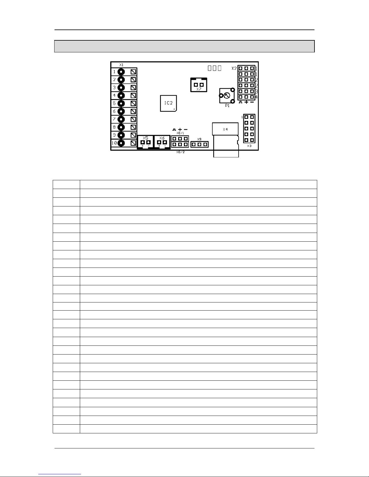
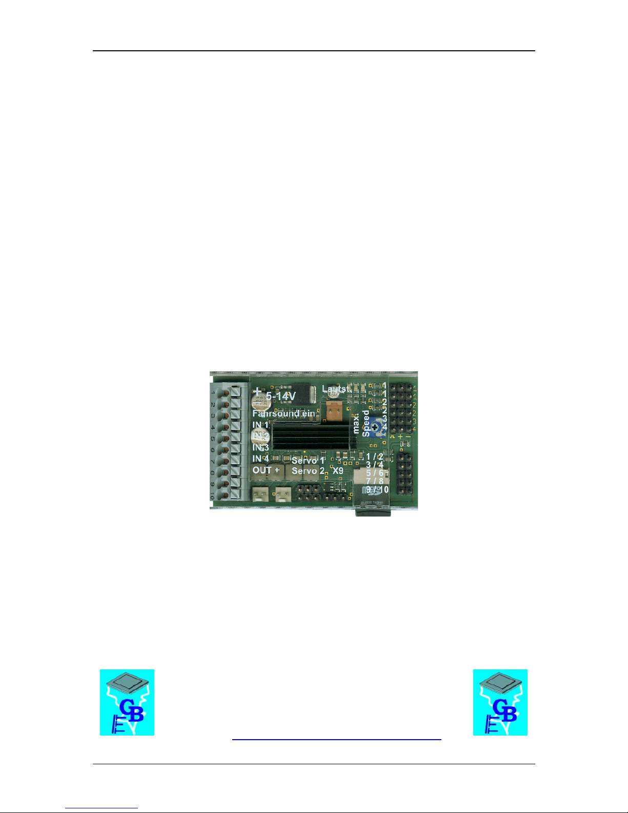
Pin assignments in digital mode
Connections on the sound module:
X1/1 Supply voltage + (5 – 14V DC)
X1/2 Supply voltage -
X1/3 Input for engine sound on/off
X1/4 Switching-input 1
X1/5 Switching-input 2
X1/6 Switching-input 3
X1/7 Switching-input 4
X1/8 Supply voltage + for outputs 1 - 12 (internally connected to X1/1)
X1/9 Switching-output 11
X1/10 Switching-output 12
X2/1 Connection for proportional channel 1 (speed 1. motor)
X2/2 Connection for proportional channel 2 (speed 2. motor)
X2/3 Connection for proportional channel 3
X2/4 Connection for proportional channel 4
X3 Switching-outputs 1 - 10
X4 Slot for Micro SD-Card
X5 Connection for loudspeaker 1
X6 Connection for loudspeaker 2 (optionally)
X7 Connection for the potentiometer for the volume control
X8/1 Connection for servo 1
X8/2 Connection for servo 2
X9 Universal Extension Interface (for example data cable, IR-transmitter diode)

D Sound module USM-RC-2
03.02.2014
BEIER-Electronic 9
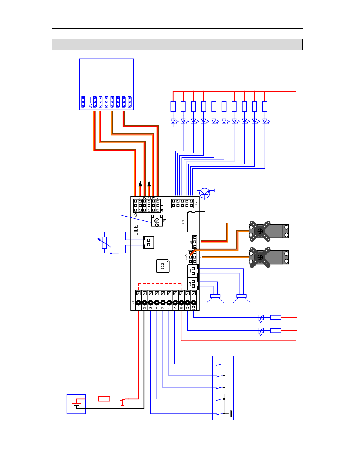
Power supply
5 - 14V DC
+
-
-
1
+
Volume
Topspeed
100k
Switch module
RC receiver
brown
Engine sound on/off
Input 1
Input 2
Input 3
Input 4
6,3A
Speed controller
Speed controller
Micro
SD
red
orange
yellow
green
blue
purple
grey
white
black
Output 1
Output 2
Output 3
Output 4
Output 5
Output 6
Output 7
Output 8
Output 9
Output 10
-
+
Servo
Speaker
2
Output 11
Output 12
1
3
5
7
9
Data cable /
IR-Diode
Servo
Wiring diagram for digital mode

D Sound module USM-RC-2
10
BEIER-Electronic 03.02.2014
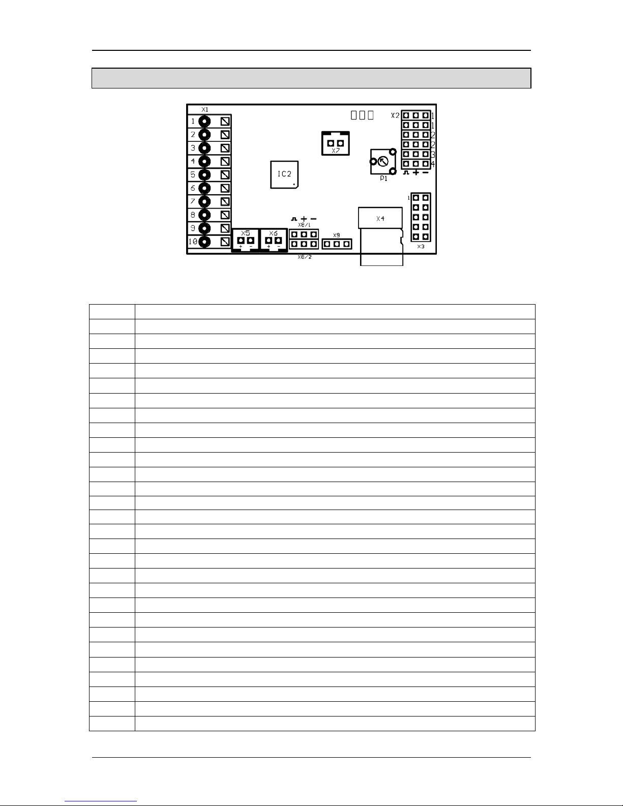
Pin assignment in analogue mode
Connections on the sound module:
X1/1 Supply voltage + (5 – 14V DC)
X1/2 Supply voltage -
X1/3 Input for engine sound on/off
X1/4 Motor 1 + (speed)
X1/5 Motor 1 - (speed)
X1/6 Motor 2 + (speed) / switching-input 5
X1/7 Motor 2 - (speed) / switching-input 6
X1/8 Supply voltage + for outputs 1 - 12 (internally connected to X1/1)
X1/9 Switching-output 11
X1/10 Switching-output 12
X2/1 Switching-input 1
X2/2 Switching-input 2
X2/3 Switching-input 3
X2/4 Switching-input 4
X3 Switching-outputs 1 - 10
X4 Slot for Micro SD-Card
X5 Connection for loudspeaker 1
X6 Connection for loudspeaker 2 (optionally)
X7 Connection for the potentiometer for the volume control
X8/1 Connection for servo 1
X8/2 Connection for servo 2
X9 Universal Extension Interface (for example data cable, IR-transmitter diode)
Table of contents