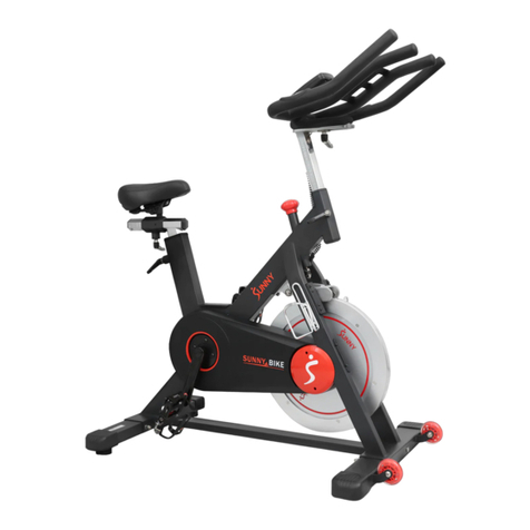
BanCon BC-B599 User manual

MAGNETIC BELT DRIVE
INDOOR EXERCISE SPIN BIKE
NOTE: Please read all precautions and instructions carefully before using this product. Keep
this manual for future reference. If you require assistance, or if you need to order replacement
parts, please contact Customer Care: [email protected]om
BC-B599 USER MANUAL
www.onebancon.com

IMPORTANT SAFETY INSTRUCTIONS
PARTS AND TOOLS
ASSEMBLY INSTRUCTIONS
BATTERY INSTALLATION & REPLACEMENT
BLUETOOTH CONNECTION
ADJUSTMENTS & MOVEMENTS
CONSOLE
SPECIFICATIONS
EXERCISE INSTRUCTIONS
WARRANTY
01
02
03
06
07
08
11
12
13
14
CONTENTS

Please keep this manual in a safe place for reference.
if the equipment is assembled, maintai ned and used properly. Ensure that all users of t he equipment are informed
of all warnings and precautions.
2.Before starting any exercise program, consult yo ur doctor to determine if you have any physical or health
conditions that could create a risk to your health and sa fety, or prevent you from using the equi pment properly.
cholesterol level.
exercising if you experience any of the following sy mptoms: pain, tightness i n your chest, irregular heartbeat,
extreme shortness of breath, or feeling lightheaded, dizzy or nauseous. If you d o experience any of these
conditions you should consult your doctor before continuing with your exercise program.
4.Keep children and pets away from the equipmen t. The equ ipment is desi gned for adult use on ly.
least 24” (0.6m) on each sid e of the machine c lear.
6.Before using the equipm ent, ensu re that the nuts, bolts, and parts such as the pedals are securely tightened.
7.Maximum user weight limit : 275 lbs. ( 125 kg). D o not use if you are over this weight .
into moving parts of the exercise equipme nt.
9.Do not operate this machine outdoors or in moist or wet locations. Keep the Pedals clean and dry.
11.Reduce the pace to slow the Pedals to a stop. Do not dism ount the bike until the Pedals h ave come to a
complete stop. Be aware that the moving Pedals can strike the backs of the legs.
12.Keep batteries away from heat source and hot surfaces.
13.The equipment is not suitable for therapeutic use.
14.To avoi d bodily injur y an d/or damage to the product or property, proper lifting and movin g are required.
equipment , or if you hear any unusual noises coming from t he equipment during exercise, discontinue us e of the
16. For sa fe storage of the machine,remove the batteries a nd fully pus h d own the Resistan ce Adjustment Handle to
IMPORTANT SAFETY INSTRUCTIONS
01

PARTS AND TOOLS
Ltem
1
2
3
4
5
6
7
Ltem
8
9
10
11
12
13
Qty
4
4
4
8
1
1
Description
PanH exagonSocket Bolt M855
PanH exagonSocket BoltM8*15
FlatWasher08.4*016
Spring Washer08.1*012.3
AlenWrench6#-5#
Spanner Sl3-S14-S15
Qty
1
1
1
1
1
1
2
Description
Main Frame
Front stabi lizer
Rear stabilizer
Adjustable Handlebar Tube
Handlebar
Console
Pedal
1 2 3 4
5 6 7
02

ASSEMBLY INSTRUCTIONS
Select the area where you are going to set up an d
operate your machine. For safe operation, the location
must be on ha rd, level s urface. All ow a workout area o f
a minimum 2.3 m x 1.8 m (90” x 69”).
Figure Ⅰ.
arrow on the box is pointing up. A s show n in Figure Ⅱ.
3.Pull the box up as shown in Figure Ⅲ.
· Read and und erstand the “important
safety instructions” before assembly.
· Collect all the pi eces necessary for
each assembly step.
· The assembly requires 2 people
Before Assembly
Basic Assembly Tips
03

01
02
10
11
08
08
08
03
10
11
Attach Front & Rear Stabilizer (N O. 2 & NO. 3) to Main
Frame (NO. 1) using 4 Pan Hexagon S ocket Bolts (NO.
8), 4 Flat Washers (NO. 10) and 4 Spring Washers ( NO.
11) as shown in the diagram. Make sure the bolts have
been tightly fastened. Tighten with Allen Wren
STEP 1
STEP 2
Let A connective Line f rom the Main Frame (NO. 1)
through Adjustable Handlebar Tube ( NO. 4) by tying L
mini cable. Loosen and pu ll out Plum Screw Kn ob,
insert A djusta ble Han dlebar Tube (NO. 4) into Main
Frame (NO. 1) and adjust to de sired height. Sec ure it in
place by reinser ting a nd tigh tening the Plum Screw
Knob. Make sure the Plum Screw K nob en gages the
holes in the Adjustable Hand lebar Tube (N O. 4).Be sure
not to pinch the connective line.
Connect A Connective Line f rom Main Frame with A
Connective Line on Handlebar (NO. 5) and put the wires
into Adjusta ble Handlebar Tube ( NO. 4).
Attach Han dlebar (NO. 5) onto Adj ustable Handlebar
Tube (NO . 4) with 4 Pan Hexagon Socket
Bolts (NO. 9) and 4 Spring Washers (NO. 11). Secure and
tighten with Allen Wrench.
NOTICE: Do not pull out A connective line with force
while assembl ing.
04

Use Spanner to remove 4 Screws on t he back o f
Console ( NO. 6), the Screws sho uld be kept in good
condition.
Connect B Conn ective Line from Console (NO. 6) with
B Connective Line on the Handlebar (NO. 5).
Secure the Console ( NO. 6) to Handlebar (NO. 5) usi ng
4 Screws that were removed, tighten with Spanner.
STEP 3
STEP 4
WARNING! Read instructions carefully as improper
assembly ma y cause permanent d amage to your bike.
NOTE: The Pedals (NO. 7 ) are mar ked “L” a nd “R” for
Left and Right.
Connect the Left & Rig ht Pedal (NO. 7) onto the Left &
Right Crank.
Left Pedal: Align the Left Pedal (NO. 7L)with the Left
Crank at 90 degrees and gently in sert the pedal into the
crank arm. Turn the pedal counter-clockwise as tightly
as you can with your ha nd. Secure with Spanner.
Right Ped al: Align the Right Peda l ( NO. 7R)with the Right
Crank at 90 degrees and gently in sert the pedal into the
crank arm. Turn the pe dal clockwise as tightly as you
can with your hand. Sec ure with Spanner.
The assemb ly is complete!
Connective Line
0 7 L
0 7 R
01
R crank
L crank
05

BATTERY INSTALLATION & REPLACEMENT
BATTERY INSTALLATION:
1. Take out 2 AA batteries from the plastic bag.
2. Press the buckle of Batter y Cover on the back
of Console (NO. 6), then remove t he Battery
Cover.
3. Install 2 AA Batteries into t he battery case on
the back o f the Conso le (NO. 54). Make sure the
batteries are instal led correctly and the
polarities are correct.
4. Press the buck le of Batte r y Cover, then put
the Batter y Cover to the back of Console (NO. 6).
1. When the display becomes dim or illegible, press the bu ckle of Battery Cover on th e back of
the Console (NO. 6), then remove the Battery Cover.
2.Remove t he 2 old AA batteries i n the batter y case and install 2 ne w AA batteries into the battery case on the
back of the Console (N O. 6).
3. Press the buckle o f Battery Cover, then put the Battery Cover back to the back of the Console ( NO. 6).
The installation is complete!
· Always change both batter ies at the same time . Do not mix batter y types and do not mix old and new batte ries.
· Be sure to remove the batter ies to prevent corrosion damage if you are not going to use th e m achine for an
extended period of time.
for children.
BATTERY REPLACEMENT:
NOTE:
06

BLUETOOTH CONNECTION
Find “More” and click th e
plus sign in the rig ht corner
Click bike icon
SHUA
logo and click
Now you’ve connected to
BANCON exercise bike
Click SH-B599
bluetooth and d evice
BC-B599P will show
up.
Notice: If there is a
code on you r digital
watch then device
starting with Z W-XXX
will show up.
07

ADJUSTMENTS & MOVEMENTS
ADJUSTING THE BALANCE
In order to achieve a smooth and comfortable ride,
you must ensure that the bike is stable and secured. If
you notice that the bike is unbalanced during use, you
should adjust the Foot Pad located beneath the Front
and Rear stabilizers. To do so, use Spanner to loosen
Hexagon Nut by turning it clockwise. With the nut
loosened, rotate the Foot Pad until it sits level with the
adjusting the Foot Pad, re-tighten the Hexagon Nut by
turning it counter-clockwise to complete the balance
adjustment of the bike. If needed, repeat this process
to adjust the remaining foot pad.
ADJUSTING THE RESISTANCE
& EMERGENCY STOP
Adjust the tension by raising the Resistance
Adjustment Handle to decrease the level of resistance.
Press Resistance Adjustment Handle down to increase
the level of resistance. Pushing down on the
Resistance Adjustment Handle to the end to enforce
the brake and stop the bike immediately.
NOTE: When the bike is not in use, be sure to lock the
Adjustment Handle to the end to prevent movement
L
o
o
s
e
s
t
08
Table of contents
Other BanCon Exercise Bike manuals