Aztech V300ATA User manual
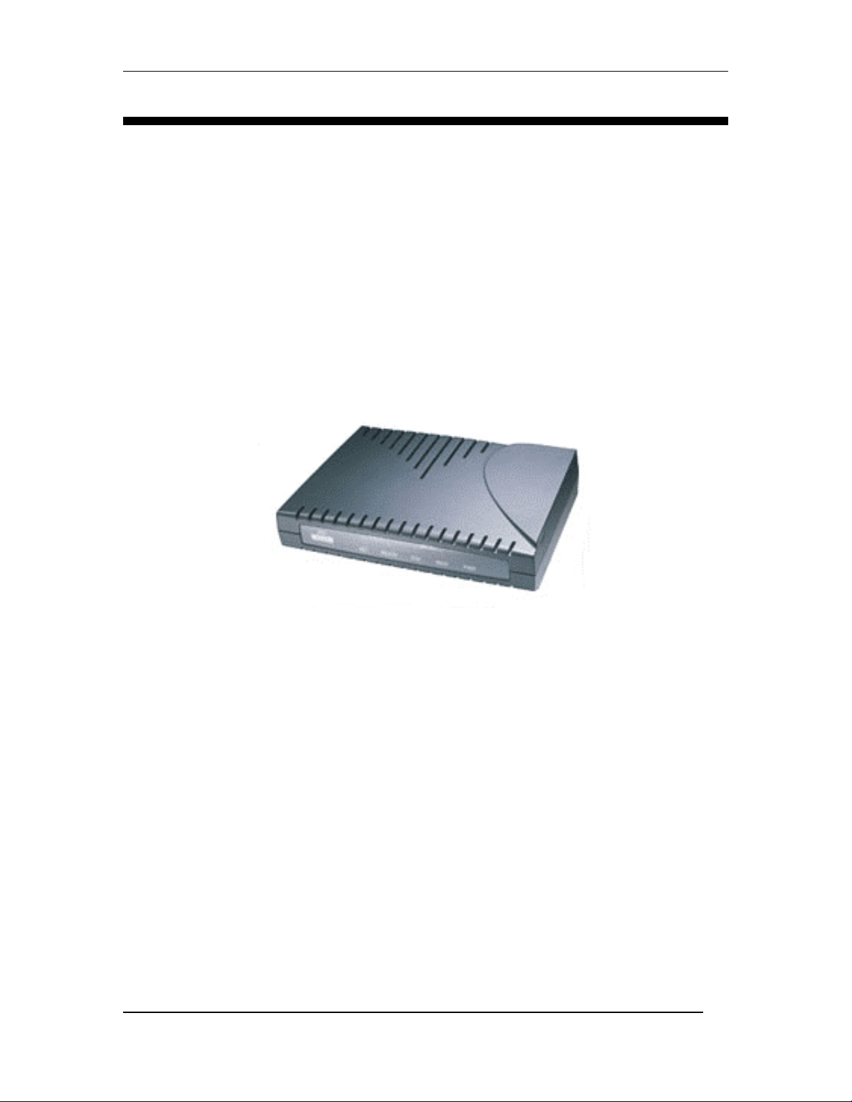
V300ATA VoIP User Manual
- i -
Web Interface User’s Guide
Version0.3
V300ATAVoIPAnalogTelephoneAdaptor

V300ATA VoIP User Manual
- ii -
Tables Of Content
1. INTRODUCTION........................................................................................................ 1
1.1 MAIN FEATURES........................................................................................................ 2
2. YOUR ANALOG TELEPHONE ADAPTOR (ATA) AT A GLANCE.................. 3
2.1 PORTS AND BUTTONS ................................................................................................. 3
2.2 LED DESCRIPTION ..................................................................................................... 3
3. INSTALLING YOUR ATA........................................................................................ 4
3.1 FOR SINGLE-USER CONNECTION .............................................................................. 4
3.2 FOR MULTIPLE-USERS CONNECTION........................................................................ 5
3.3 FOR COMPANY NETWORK CONNECTION.................................................................... 6
4. SETTING UP YOUR V300ATA ROUTER FUNCTIONALITY VIA GUI .......... 7
4.1 ACCESS TO V300ATA GUI....................................................................................... 7
4.2 SETUP MODE.............................................................................................................. 7
5BASIC MODE........................................................................................................... 8
5.1 OVERALL STATUS.................................................................................................... 9
5.2 LAN STATUS......................................................................................................... 10
5.3 DHCP CLIENT STATUS.......................................................................................... 11
5.4 PPP STATUS .......................................................................................................... 12
5.5 TCP STATUS.......................................................................................................... 13
5.6 SYSTEM LOG.......................................................................................................... 14
6 BASIC CONFIGURATIONS................................................................................... 15
6.1 WAN CONFIGURATION.......................................................................................... 15
6.2 LAN & DHCP CONFIGURATION........................................................................... 18
6.3 NAT CONFIGURATION........................................................................................... 20
6.4 PORT FORWARDING CONFIGURATION.................................................................... 22
6.5 BRIDGE FILTERING................................................................................................ 23
6.6 DNS CONFIGURATION........................................................................................... 24
6.7 SAVE SETTINGS / REBOOT ..................................................................................... 25
7. ADVANCED MODE................................................................................................. 27
7.1 ATA CONFIGURATION............................................................................................. 27
7.2 SIP SERVICE PROVIDER CONFIGURATION................................................................ 28
7.2.1 SIP Service Provider........................................................................................ 28
7.3 ATA LOGIN ACCOUNT CONFIGURATION................................................................. 30
7.4 ATA TIMER CONFIGURATION.................................................................................. 32
7.5 COUNTRY SPECIFIC RING & TONES CONFIGURATION............................................ 33
7.6 ATA MISC CONFIGURATION ................................................................................. 35
8. ADMIN PRIVILEGE................................................................................................ 38

V300ATA VoIP User Manual
- iii -
8.1 ROUTE TABLE.......................................................................................................... 38
8.1.2 Route Configuration......................................................................................... 39
8.2 BRIDGE MAC TABLE............................................................................................... 40
8.3 RIP SYSTEM WIDE CONFIGURATION ....................................................................... 40
8.4 DMZ CONFIGURATION............................................................................................ 43
8.5 SNTP CONFIGURATION ........................................................................................... 44
8.6 MISCELLANEOUS CONFIGURATION.......................................................................... 45
8.7 ADMIN USERNAME / PASSWORD CONFIGURATION .................................................. 47
8.8 RESET TO DEFAULT ................................................................................................. 47
8.9 FIRMWARE UPDATE ................................................................................................. 48
8.10 SAVE / REBOOT...................................................................................................... 49

V300ATA VoIP User Manual
- 1 -
1. Introduction
Thank you on your purchase of the VoIP V300ATA
The V300ATA VoIP Analog Telephone Adaptor (ATA) products are standards-based
communication devices that deliver true, next-generation voice-over-IP (VoIP) terminations
to residences worldwide. Internet telephony employs a variety of protocols, including Real-
time Transport Protocol (RTP) for transport of multimedia data and Session Initiation
Protocol (SIP) for call signaling and control.
The V300ATA series are mixed-environment adaptors that interface legacy analog
telephones, fax machines, analog conference telephones and other analog devices to IP based
telephony networks thereby allowing users and ISPs to protect prior investments in analog
phones, fax machines, and speakerphones, and migrate to IP at their own pace. These
products address the needs of small-office environments, and the emerging VoIP voice
services whereby ISPs value add their ADSL or Cable Modem offering with VoIP services
by turning their analog devices into IP devices.
The V300ATA is installed at the subscriber's premises and supports one voice ports with a
POTS bypass for using the existing POTS primary line. The V300ATA supports 2
10/100BaseT Ethernet ports. This adaptor can make use of existing broadband pipes such as
digital subscriber line (DSL), fixed wireless and cable modem deployments. In addition, the
V300ATA has an internal Ethernet switch with routing capability, which allows for a direct
connection to another 10/100BASE-T Ethernet network via an RJ-45 interface, with single
LAN connectivity for both the V300ATA and a co-located PC or other Ethernet-based
device.
By turning any analog telephone into an IP telephone, the V300ATAs address the needs of
the emerging market of "second-line" residential voice-over-IP (VoIP) services. Broadband
service providers can now deploy voice services quickly to grow revenues and facilitate the
development of new services.

V300ATA VoIP User Manual
- 2 -
1.1 Main Features
• Call Out & Call In
• Voice over IP c all (through Gatekeeper)
• PSTN phone call (bypass I )
• IP address calling (Future Firmware Upgrade)
• Conference call (Ad Hoc Conference Call) (Up to Three Participants)
• Call features
• Call Waiting
• Call Hold
• Call Forward
• Call ID
• Setup & Configuration
• Auto (remote) Software Upgrade
• Web Based Configuration
• Password Protection for Web Configuration
• Audio Codec Feature
• Supports G.711, G.723,G.726,G.729a
• Voice Activity Detection
• Silence Compression
• Comfort Noise Generation
• Echo Cancellation
• Jitter Provisioning
• Protocols
• SIP (Default)
• T.38 Fax over IP support
• DHCP client
• DNS client
• Static IP
• FTP
• HTTP Server for Web Management (Firmware Upgrade)

V300ATA VoIP User Manual
- 3 -
2. Your Analog Telephone Adaptor (ATA) at a glance
The V300ATA may have different ports and LEDs. Let’s take a look at the different options.
Depending upon your model, it may have some or all of the features listed below
2.1 Ports and buttons
12V Power is where you connect the power. Make sure to observe the proper power
requirements. The require power is 12 volts.
Modem: 10/100 Base-T RJ-45 socket which is to be connected to your ADSL or Cable
modem.
Ethernet: 10/100 Base-T RJ-45 socket which is to be connected to your PC or to a
hub/switch if you want multiple PC access.
Reset and Restore to Factory Defaults:The restore to factory defaults feature will set the
V300ATA to its factory default configuration by resetting the V300ATA. You may need to
place the V300ATA into its factory defaults if the configuration is changed, you will lose the
ability to interface to the V300ATA via the web interface, or following a software upgrade,.
To reset the V300ATA, simply press the reset button for about ~ 8 seconds. The V300ATA
will be reset to its factory defaults and after about 30 ~ 40 seconds the V300ATA will
become operational again.
Phone: RJ-11 telephone socket, which is to be connected to an PSTN analog phone.
Line: RJ-11 telephone socket, which is to be connected to telephone wall socket. In by-pass
mode, the PSTN signal will be send to the analog phone
2.2 LED description
IN USE: Lights up when the device is powered up and the telephone handset is off-hook
READY: Lights up when VoIP service is in operational mode.
ETH: Lights up when Ethernet link is detected and blinks according to LAN Ethernet traffic.
WAN: Lights up when WAN link is detected and blinks according to WAN traffic.
PWR: Lights up when device is power on.

V300ATA VoIP User Manual
- 4 -
3. Installing your ATA
3.1 For Single-User Connection
The following shows a typical single-user connection. You need to have a ADSL modem or
Cable modem before you can connect to the ATA. It can be placed behind router or straight
from the moem. Check if your Computer/Notebook has an Ethernet Port. The Telephone set
is connected to the RJ-11
3.1.1 ADSL Connection
www
ADSL
Modem / Router
Computer/Network with
Ethernet NetworkCard
Telephone Set
internet V300ATATelephone
WallSocket
POTSSplitter
Figure 3-1: Connection via ADSL for single User
3.1.2 Cable Connection
www
Cable
Modem Computer/Network with
Ethernet NetworkCard
Telephone Set
internet
Telephone
WallSocket
Cable
Point
Cable/DSL
Router V300ATA
Figure 3-2: Connection via Cable for single User

V300ATA VoIP User Manual
- 5 -
3.2 For Multiple-Users Connection
If you want to connect more than a one Computers/Notebooks connection, you may connect
the ATA to a switch/hub; the switch/hub will then be connected to the other
Computers/Notebook. The diagram below shows multiple-users connection using ADSL.
Cable users connection is similar to the ADSL, by using an Ethernet (RJ-45) cable, connect it
from V300ATA to a Hub/Switch.
Hub/Switch
www
Computer/
Network with
EthernetNetwork
Card
Telephone Set
internet Telephone
WallSocket
POTSSplitter
Computer/
Network with
EthernetNetwork
Card
ADSL
Modem / Router
V300ATA
Figure 3-3: Connection via ADSL /Cable or multiple users
For details on the connection and types of Ethernet Network cable to use with the Ethernet
Hub/Switch, please refer to the user guide that comes with your Ethernet Hub/Switch.

V300ATA VoIP User Manual
- 6 -
3.3 For Company Network Connection
Please seek advise from your company’s Network Administrator, to open ports 5000,5060
for the VoIP functions.
www
Computer/Network with
Ethernet NetworkCard
Telephone Set
internet
Telephone
WallSocket
Company
Network
Figure 3-4: Connection via Company Network

V300ATA VoIP User Manual
- 7 -
4. Setting up your V300ATA router functionality via GUI
4.1 Access to V300ATA GUI.
To configure your V300ATA, you need to login to the device using a web browser.
i) Connect the V300ATA as shown in the Section 3.
ii) Launch your web browser.
iii) Type in 10.0.0.99 at the Address bar and press Enter key.
(Note: 10.0.0.99 is the default IP address for Router).
4.2 Setup Mode.
Upon successfully logging in, the Setup mode screen as shown below is displayed.
Note :
Please refer the Easy Start Manual, ”Step 5 VoIP Configuration Setup” for the details
Figure 4.1: Setup Page
Table of contents