
Avid Technology SmartCal Series User manual

AVID
AVDSB-0026-EN-1307
Contents
1 Introduction 2
1.1 Description of SmartCal positioner 2
1.2 Principle of operation 2
2 Initial setup 4
2.1 Mounting positioner on a rotary
actuator 4
2.2 Mounting remote positioner on a
rotary actuator 5
2.3 Wiring the remote sensors to the
positioner 6
2.4 Mounting positioner on a linear
actuator 7
2.5 Mounting remote positioner on
alinear actuator 9
2.6 Pneumatic connection 10
2.7 Electrical connection 11
3 Calibration with the display 12
3.1 Enter calibration 12
3.2 Configure the positioners
parameters 12
3.3 Automatic calibration 13
3.4 Advanced calibration (optional) 13
3.5 Exit calibration 14
3.6 Manual override of input signal 14
3.7 Description of menus 15
3.8 Description of functions 16
4 Calibration with pc application 18
4.1 Configuration of the SmartCal
parameters 19
4.2 Measurement data 20
4.3 Diagnosis 21
4.4 Additional functions 22
4.5 Print 23
5 Trouble shooting 24
5.1 Preliminary checks 24
5.2 FAQ 25
6 Specifications 26
7 Error codes 26
8 Exploded parts list 27
Appendices
A Procedure to adjust Err 3 setting 28
B Procedure to remove electronics
cover and electronic canister 29
C Setting the transmitter output
failcurrent 30
AVID SmartCal valve positioner
Installation & operating instructions
Installation and operating instructions for the AVID
SmartCal intelligent valve positioner
Note: Air supply to the positioner
mustbe clean, dry, oil free instrument
air(5microns) per ISA-S7.3 and
ISO8573-1. Maximum supply pressure
is 8.3 bar. Allpneumatic connections
are1/4” NPT or G 1/4 ISO 228.
www.cranecpe.com
D Procedure to check transducer
operation 31
E General maintenance standard
flow 32
F Grounding schematic 33
G Pneumatic manifold diagram 34
H Control schematic for wiring of
intrinsically safe SmartCal for
ATEX&IECEX 35
I Control schematic for wiring of
intrinsically safe SmartCal for
US&Canada 37
J Procedure to reset the EEPROM
tofactory settings 41
K HART® Communicator menu
flowchart 42

page 2
1 Introduction
1.1 Description of SmartCal positioner
The SmartCal valve positioner is an electro-pneumatic servo system that continuously controls the
position of a valve based on a 4 to 20 mA input signal. The SmartCal is an instrument that
derives its power directly from a control systems current loop. The instrument senses valve
position via a non-contact Hall effect sensor and controls valve position through a current to
pressure transducer.
Calibration of the SmartCal can transpire by two means. Non-HART® calibration is through an
on-board keypad. Communication using HART® protocol allows calibration and access to on-line
diagnostics via a Rosemount® 275 hand-held terminal or through FDT/DTM software.
The positioner has a local liquid crystal display which indicates valve position and set-point in
percentage open. It also indicates whether the positioner is in calibration mode.
The SmartCal has the capability to monitor operation. If a failure condition occurs, an error
message is displayed on the local liquid crystal display.
1.2 Principle of operation
Unlike conventional positioners, the SmartCal positioner feeds back valve position without the
need for linkages, levers, or rotary and linear seals. Position sensing is performed totally by
non-contacting means, permitting use of advanced control strategies where knowledge of valve
position is used in predictive and other algorithms. By the integration of multiple components into
a singular, cost efficient unit, microprocessor-based intelligence can now be used to implement
advanced functions such as early warning diagnostics and fugitive emissions monitoring.
The SmartCal positioner provides intelligence for the control valve through a microprocessor-based
diagnostic system utilizing the HART® protocol. Accurate measurement of valve stem position,
input signal, actuator pressure and travel time can be recorded during normal operation, thereby
providing information for control valve signature generation.
AVID SmartCal valve positioner
Installation & operating instructions
LINEAR VALVE
Magnet
Magnet
Sensor
Magnet
Valve stem
Sensor
Magnet

Non-contact position feedback
To provide consistently accurate performance information, all linkages, levers and connecting rods,
from the positioner to the control valve have been eliminated from the design. Valve position sensing
is performed totally by non-contacting means based upon characterisation of flux strength as a
function of position.
Remote position control
Since valve position feedback to the SmartCal positioner is accomplished by non-contacting means,
the SmartCal has the unique ability to be mounted remotely (up to a distance of 15 m or 50 feet)
from the device it is controlling. In the event the control valve is located in either a high vibration
or extremely corrosive environment, the non-contact position feedback feature allows for isolated
placement of the positioner.
Local LCD
The SmartCal positioner is supplied with HART® interface and a 3-button keypad interface. All
SmartCal positioners are furnished with a multi-line LCD, and allow for automated calibration of
the positioner. The local LCD provides a multitude of onsite diagnostic information. The displayed
information will show the setpoint and position as a percentage. The range of values displayed are
from 0.0% to 100.0%. Displayed resolution is in 0.1% increments, however, internal calculations
are maintained at higher precision.
On-board sensors
The SmartCal positioner has the capability to monitor its operation. If an error or failure condition
occurs, it will be displayed on the local LCD, through the HART® interface and displayed on a hand
held terminal or at a PC maintenance station. Note: Error codes are denoted on a label affixed to
the LCD flip-up protective cover.
Local keypad
All positioners are provided with a 3-button keypad. The keypad is provided for zero and span
adjustments, as well as valve characterization and gain adjustments.
Intelligent calibration (HART® protocol)
The SmartCal positioner responds to HART® commands for seeking the ‘valve closed’ position
and assigns an instrument signal of 4 mA to this position. The counterpart of the operation for a
full open state is implemented next by setting the span value. Action reversal is also configured.
Additionally, provisions are made for altering internal servo loop tuning via the HART® link. In
this manner, positioner performance may be optimized with a wide combination of valves and
actuators.
Negligible bleed
Designed to consume the least possible amount of control air at steady state, the SmartCal
positioner can greatly reduce the air consumption of your process and reduce the demand on
instrument air compressors. To increase reliability, the SmartCal employs a patented lapped spool
and floating sleeve design. This balanced construction relies on an air bearing which eliminates
any metal to metal contact.
page 3
AVID SmartCal valve positioner
Installation & operating instructions

page 4
AVID SmartCal valve positioner
Installation & operating instructions
2 Initial setup
Condition 2:
Actuator fails in a counter clockwise direction
(Turns clockwise from fail position).
Spring return
Output port 2 is plugged.
Output port 1 is piped to turn the actuator
clockwise.
Double acting
Output port 2 is piped to turn the actuator
counter clockwise.
Output port 1 is piped to turn the actuator
clockwise.
Semi-circle faces
the front of the
positioner
Actuator
(in fail position)
ModMount
Supply
Port 1
Port 2
Triangle faces
the front of the
positioner
Actuator
(in fail position)
ModMount
Supply
Port 1
Port 2
TURNS
COUNTER CLOCKWISE
(from fail position)
TURNS CLOCKWISE
(from fail position)
2.1 Mounting positioner on a rotary
actuator
Condition 1:
Actuator fails in a clockwise direction
(Turns counter clockwise from fail position).
Spring return
Output port 2 is plugged.
Output Port 1 is piped to turn the actuator
counter clockwise.
Double acting
Output port 2 is piped to turn the actuator
clockwise.
Output port 1 is piped to turn the actuator
counter clockwise.
Figure 2-1
* Note
1. Drive insert must be provided with
Keystone actuators for ModMount
installations.
2. Drive insert may need to be disengaged
and rotated 90° to allow for proper
mounting.
* Drive insert
* Drive insert

Condition 2:
Actuator fails in a counter clockwise direction
(Turns clockwise from fail position).
Spring return
Output port 2 is plugged.
Output port 1 is piped to turn the actuator
clockwise.
Double acting
Output port 2 is piped to turn the actuator
counter clockwise
Output port 1 is piped to turn the actuator
clockwise
Semi-circle faces
side with the
conduit entry
Actuator
(in fail position)
Mounting assembly
Conduit entry
Positioner sensor
Triangle faces the
side with the
conduit entry
Actuator
(In fail position)
Mounting assembly
Conduit entry
Positioner sensor
TURNS
COUNTER CLOCKWISE
(From fail position)
TURNS CLOCKWISE
(From Fail Position)
2.2 Mounting remote positioner on a
rotary actuator
Condition 1:
Actuator fails in a clockwise direction
(Turns counter clockwise from fail position).
Spring return
Output port 2 is plugged.
Output port 1 is piped to turn the actuator
counter clockwise.
Double acting
Output port 2 is piped to turn the actuator
clockwise.
Output port 1 is piped to turn the actuator
counter clockwise.
Figure 2-2
* Note
1. Drive insert must be provided with
Keystone actuators for ModMount
installations.
2. Drive insert may need to be disengaged
and rotated 90° to allow for proper
mounting.
* Drive insert
* Drive insert
page 5
AVID SmartCal valve positioner
Installation & operating instructions
page 6
AVID SmartCal valve positioner
Installation & operating instructions
Position sensor
(mounted on actuator
as described in Section 2.2)
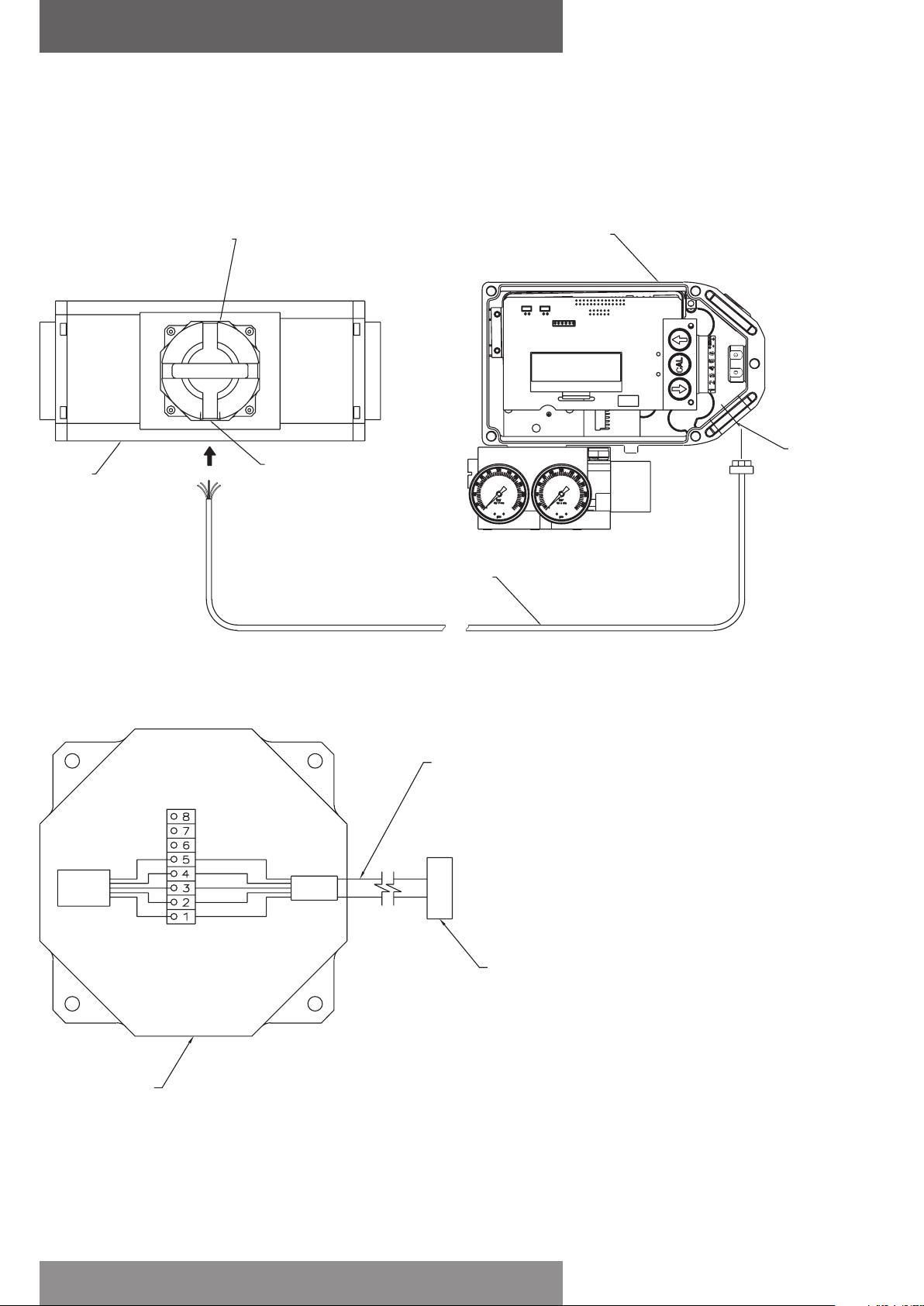
2.3 Wiring the remote sensors to the positioner
Mount positioner at a remote location. Remove the electronic canister cover by unscrewing 2
mounting screws. Wire the positioner sensors back to the positioner using the cable provided
(seeFigure 2-3).
(4) Conductor cable
(cut to required length
and run through conduit)
M20x1.5
(1/2” NPT)
Positioner
sensor
HALL
EFFECT
SENSOR
SHIELD (YELLOW)
BLACK
GREEN
RED
WHITE
Pin connector
(to display board
of positioner)
(4) Conductor
shielded cable
3/4” NPT
Wiring schematic
Figure 2-3
Actuator
(top view)
Positioner
(mounted remote from
actuator at users discretion)

1.5 mm (1/16”)
1.5 mm (1/16”)
page 7
AVID SmartCal valve positioner
Installation & operating instructions
Magnet assembly
SmartCal assembly
housing
Centerline of
magnetic pick-up unit
(position sensor)
Actuator split block
(atlower limit of
travel)
Actuator
centerline
Actuator split block
(atupper limit of travel)
Stroke/2
Stroke/2
Full
stroke
Upper limit of travel
Location of centerline
Lower limit of travel
Actuator yoke
Actuator split block
Magnet assembly
Mounting bracket
Magnetic pick-up unit
(position sensor)
SmartCal assembly
2.4 Mounting positioner on a linear
actuator
Step 1. Mount the magnet assembly to the
stem of the actuator. A coupler block normally
is needed to extend the magnet assembly
outside the yoke area and into the sensing
range of the magnetic pick-up unit.
Step 2. Fasten the mounting bracket to the
actuator.
Step 3. Mount the positioner to the mounting
bracket. The positioner should be mounted so
the magnetic pick-up unit of the positioner is
centered between the limits of the magnetic
assembly’s stroke. After mounting the
positioner, the magnet assembly should
be within 3 mm (1/8”) from the back of
the positioner (1.5 mm (1/16”) is ideal),
(SeeFigure2-4 A)
Note
For Fisher actuators model 657 & 667 sizes 34
thru 70, can supply a slotted
mounting kit design. This will allow the user
to easily center the positioner sensor between
the limits of the magnet assembly’s stroke.
Figure 2-4 A

page 8
AVID SmartCal valve positioner
Installation & operating instructions
2.4.1 To center the positioner
1. Stroke the actuator to its upper limit and place a mark on the actuator’s yoke that lines up with
the red arrow on the magnet assembly.
2. Stroke the actuator to its lower limit and place a mark on the actuator’s yoke that lines up with
the red arrow on the magnet assembly.
3. Place a third mark on the yoke centered between the upper and lower limit marks.
4. Lastly, mount the positioner to the bracket so that the positioner sensor (nose) of the SmartCal
lines up with the midpoint mark. (See Figure 2-4 B)
Figure 2-4 B
Magnet assembly
(atupper limit of travel)
Magnet assembly
(atlowerlimit of travel)
Lower limit of travel mark
Midpoint of travel mark
Upper limit of travel mark
Actuator yoke
SmartCal

page 9
AVID SmartCal valve positioner
Installation & operating instructions
Actuator
Mounting bracket
Position sensor
Conduit entry
2.5 Mounting remote positioner on a linear actuator
Step 1. Mount the magnet assembly and bracket to the actuator as described in Section 3.3 Step 1.
Step 2. Mount the position sensor housing so that the conduit entry faces away from the
diaphragm or cylinder. (See Figure 2-5 A)
Step 3. Mount positioner at a remote location.
Note
For Fisher actuators model 657 & 667 sizes 34
thru 70, supplies a slotted mounting
kit design, to ease the mounting process. This
will allow the user to easily center the
positioner sensor between the limits of the
magnet assembly’s stroke.
Figure 2-5

2.6 Pneumatic connection
Single acting actuator (spring return):
For single acting actuators outlet port 2 is to be plugged. Outlet port 1 is to be piped to the
actuator inlet port that acts against the spring. (Increasing control signal causes pressure to
increase in outlet port 1 of the positioner).
Double acting actuator (double return):
For double acting actuators outlet port 2 is piped to drive the actuator towards the fail position.
Outlet port 1 is piped to drive the actuator away from the fail position. (Increasing control signal
causes pressure to increase in outlet port 1 of the positioner and pressure to decrease in outlet
port 2 of the positioner).
Note: Air supply to the positioner must be clean, dry, oil free instrument air (5 microns) per
ISA-S7.3 and ISO 8573-1. Maximum supply pressure is 8.3 bar. All pneumatic connections are
1/4”NPT or G 1/4 ISO 228.
Inlet port gage
Outlet port 1 gage
Outlet port 1
Outlet port 2
Inlet port
1. Single acting/spring return (plug outlet port 2) increasing control signal causes pressure to
increase in outlet port 1.
2. Double acting/double return (pipe outlet port 2 to drive actuator towards the desired failure
direction) increasing control signal causes pressure to decrease in outlet port 2 and pressure to
increase in outlet port 1.
Notes:
On loss of power pressure fails to outlet port 2.
Figure 2-6
page 10
AVID SmartCal valve positioner
Installation & operating instructions
Table of contents
Other Avid Technology Valve Positioner manuals


Popular Valve Positioner manuals by other brands


Parker
Parker MX80L series product manual

Westlock
Westlock Quantum 2800 Installation & operating instructions

Samson
Samson 3730-0 Mounting and operating instructions

Samson
Samson TROVIS 3730-3 Mounting and operating instructions

ESCO Technologies
ESCO Technologies ETS LINDGREN 2302-001 user manual

SMC Networks
SMC Networks IP8000 manual

Samson
Samson FOUNDATION 3730-5 Mounting and operating instructions

Samson
Samson TROVIS SAFE 3731-3 Mounting and operating instructions

Flowserve
Flowserve Logix 3400MD User instructions

halstrup-walcher
halstrup-walcher HIPERDRIVE instruction manual

ABB
ABB TZIDC Commissioning instructions

Samson
Samson FOUNDATION 3730-5 Mounting and operating instructions