Autrol ATT2100 User manual

ATT 2100 / ATT 2200 Smart Temperature Transmitter Operation Manual M2X00-E01H
*Information on this manual can be changed without an advance notice.
ATT 2100/ATT 2200
Smart Temperature Transmitter
Operation Manual
AUTROL Series Operation Manual : M2X00-E01H
www.autroltransmitter.com
Autrol Corporation of America

ATT 2100 TEMPERATURE TRANSMITTER Operation Manual M2100-REV-G
1
ATT 2100 Smart Temperature Transmitter
This manual is for general user to understand the installation and operatation of ATT
2100 / ATT2200 Smart Temperature Transmitter efficiently.
Before handling Autrol series device, all users have to be fully understand to control or get
some technical support.
Information on this manual can be changed without an advance notice.
www.autroltransmitters.com
796 Tek Drive, Crystal Lake, IL 60014, USA
Direct : +1 847-857-6062 | +1 847-779-5000
Fax : +1 847-655-6062

ATT 2100 TEMPERATURE TRANSMITTER Operation Manual M2100-REV-G
2
Table of Contents
1. INTRODUCTION
1-1. USING THIS MANUAL
1-2. OVERVIEW OF TRANSMITTER
1-3. SOFTWARE COMPATIBILITY
1-4. TRANSMITTER COMPONENTS
2. HANDLING CAUTIONS
2-1. UNPACKING
2-2. MODEL AND SPECIFICATIONS CHECK
2-3. STORAGE
2-4. SELECTING THE INSTALLATION LOCATIONS
2-5. WATERPROOFING OF CABLE conduct CONNECTIONS
2-6. RESTRICTIONS ON USE OF RADIO TRANSCEIVER
2-7. INSULATION RESISTANCE TEST AND DIELECTRIC STRENGTH TEST
2-8. INSTALLATION OF EXPLOSION PROTECTED TYPE TRANSMITTER
2.9 EMC CONFORMITY STANDARDS
3. TRANSMITTER FUNCTIONS
3-1. OVERVIEW
3-2. SAFETY MESSAGE
3-3. WARNING
3-4. WIRING

ATT 2100 TEMPERATURE TRANSMITTER Operation Manual M2100-REV-G
3
3-5. FAIL MODE ALARM
3-6. EEPROM-WRITE ENABLE/DISABLE MODE JUMPER
3-7. CONFIGURATION OF ALARM AND SECURITY JUMPER PROCEDURE
3-8. CONFIGURATION OF ZERO AND SPAN PROCEDURE
3-9. CONFIGURATION OF ZERO POINT ADJUSTMENT PROCEDURE
3-10. COMMISSIONING ON THE BENCH WITH HHT
3-11. LCD MESSAGES
4. INSTALLATION
4-1. OVERVIEW
4-2. SAFETY MESSAGE
4-3. WARNING
4-4. COMMISSIONING ON THE BENCH WITH HAND-HELD TERMINAL
4-5. GENERAL CONSIDERATIONS
4-6. ELECTRICAL CONSIDERATIONS
4-7. POWER SUPPLY
4-8. WIRING
4-9. LOOP
4-10. WIRING INSTALLATION
4-11. GROUNDING
4-12. POWER SUPPLY VOLTAGE AND LOAD RESISTANCE
4-13. TEMPERATURE SENSOR INSTALLATION
4-14. MECHANICAL CONSIDERATIONS

ATT 2100 TEMPERATURE TRANSMITTER Operation Manual M2100-REV-G
4
4-15. ENVIRONMENTAL CONSIDERATIONS
5. ON-LINE OPERATION
5-1. OVERVIEW
5-2. SAFETY MESSAG
5-3. CHECK OUTPUT
5-4. BASIC SETUP
5-5. DETAILED SETUP
5-6. INFORMATION VARIABLE SETUP
5-7. DIAGNOSITICS AND SERVICES
5-8. CALIBRATION
6. MAINTENANCE
6-1. OVERVIEW
6-2. SAFETY MESSAGE
6-3. HARDWARE DIAGNOSTICS
6-4. HARDWARE MAINTENANCE
APPENDIX I
ATT 2100 SMART TEMPERATURE
TRANSMITTER LCD DISPLAY CODE

ATT 2100 TEMPERATURE TRANSMITTER Operation Manual M2100-REV-G
5
Chapter 1 Introduction
The ATT 2100/ATT 2200, Smart Temperature Transmitter is correctly calibrated at the factory before
shipment. To ensure correct and efficient use of the instrument, please read this manual
thoroughly and fully understand how to operate the instrument before operating it
①The contents of this manual are subject to change without prior notice.
②All rights r
eserved. No part of this manual may be reproduced in any form without
Autrol’s written permission.
③If any question arises or errors are found, or if any information is missing from this manual,
please inf
orm the nearest Autrol sales office.
④The specifications covered by this manual are limited to those for the standard type under the
specified model number break-down and do not cover custom-made instrument.
⑤Please note that changes in the specifications, construction, or component parts of the
instrument may not immediately be reflected in this manual at the time of change, provided that
postponement of revisions will not cause difficulty to the user from a functional or performance
standpoint.
1-1 Using This Manual
The Chapters in this operating manual provide information on installing, operating, and
maintaining devices from the AUTROL Model ATT 2100 Smart Temperature Transmitter. The Chapters
are organized as follows.
Chapter 2 Handling Cautions
Chapter 2 provides instructon on unpacking, Storage and Selecting the installation locations.
Also, installation of explosion protected type transmitters at site and about EMC Conformity standards.
Chapter 3 Transmitter Functions
Chapter 3 contains in consideration of handling Model APT3100 Smart Pressure Transmitters.
Chapter 4 Installation
Chapter 4 contains mechanical, environment consideration and electrical installation
instructions on the Model ATT 2100 Smart Temperature Transmitters.
Chapter 5 On-line Operation
Chapter 5 describes the configuration the parameter how to use variety of the Model ATT
2100 Smart Temperature Transmitters' software fucntion and configuration.
Chapter 6 Maintenance
Chapter 6 contains hardware diagnostics, troubleshooting and maintenace task.

ATT 2100 TEMPERATURE TRANSMITTER Operation Manual M2100-REV-G
6
1.2 Overview of Transmitter
Autrol® Smart Temperature Transmitter based in a microprocessor is the temperature transmitter, has
temperature sensors such as Thermocouple, RTD, mV, Resistance for temperature
measurement. ATT 2100 has a true draft analog range from 0 to 20mA offering that featuresthat a
temperature range or after convert analog range to HART (Communication) digital signal transmit for
control systems like DCS, PLC. This Model has explosion protected type and high precision, better
reliability and is available on digital communication for the use remotes communication system.
This transmitter is enabled in HART communication with Host, HHT (HART Hand-Held Terminal) or PC
Configurator. Thus, transmitter various variables in host is enable to be changed, configured and
tested calibrated by users. For the HART Communication between DC Power Supply and Transmitter
has to terminate 250~ 600 Ohm.
1.3 Software Compatibility
Autrol® Smart Transmitter's software isimplemented and complemented if necessary. Uses of the
transmitter will not be a compatibility software is contained in the host of the HHT(Model 275 HART
Communicator). In this case contact us for software DD(Device Descriptor) to be able to use with the
transmitter,you must to use loading in HHT, etc.
There may be some differences on supported functions as to Firmware Revision of transmitter. This
manual is based on Firmware Revision 58. Function deviations as to firmware Revision are same
as under box
FUNCTION
Function Supports
ZERO / SPAN Botton Autrol PC/PDA HART 275/375
Before Rev. 58 Rev. 58
ZERO/SPAN ●●●●
ZERO TRIM ●●●●
ZERO Adj ●●●●
Units set ⅹ●●●
Range set ⅹ●●●
Damping set ⅹ●●●
LCD Decimal set ⅹ●●∆
●: Supported.
ⅹ: Not Supported
∆: Supported but update required

ATT 2100 TEMPERATURE TRANSMITTER Operation Manual M2100-REV-G
7
1.4 Transmitter Components
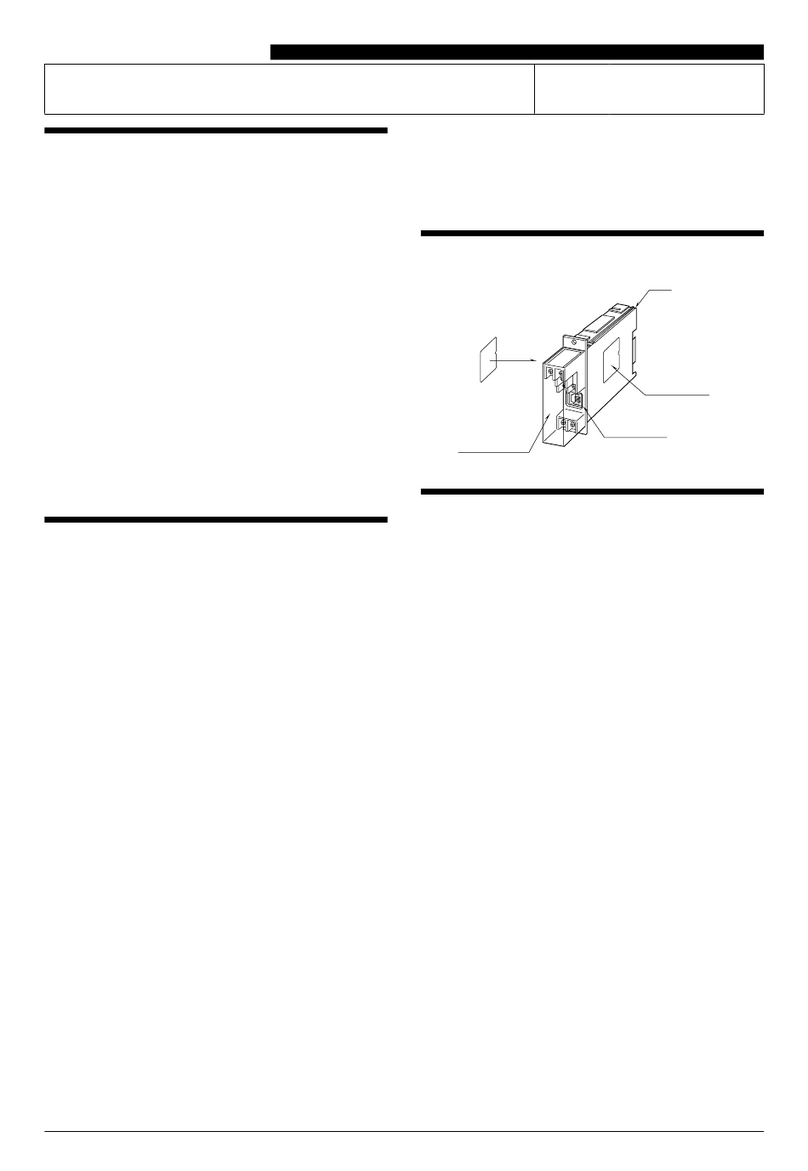
The components and figure of Autrol Smart Temperature Transmitter ATT 2100 is as follow.
Figure 1-1. Model ATT 2100 Transmitter Exploded View (Housing)
Figure 1-2. TRANSMITTER COMPONENTS

ATT 2100 TEMPERATURE TRANSMITTER Operation Manual M2100-REV-G
8
Chapter 2 Handling Cautions
This chapter consists of cautions for transmitter handling and storage, selection of installation locations,
insulation and explosion structure, etc.
[Quick Reference Manual]
Step Jog Job Details Instrument
1 Unpacking a) Unpack transmitter packing
2 Model and
Specifications
Check
a) Make sure whether the delivered transmitter is
same as options attached on its nameplate
3 Storage a) Places not exposed to water, non-vibration and
non-impact area
b) Ambient temperature 25 deg C and relative
humidity 65% RH
Sensor Element
connection terminal
Sensor Element
connection terminal

ATT 2100 TEMPERATURE TRANSMITTER Operation Manual M2100-REV-G
9
4 Calibration on a
Calibration Room
a) Basic Configuration
b) Input RTD &TC, TC Cold Juction Calibration, DAC
Trim
HHT,
Galvanometer
5 InstallationLocation a) Where ambient temperature is not fluctuated
b) Where corrosion happens by chemical materials,
etc.
c) Where vibration and impact is not severe
d) Where non-explosion area is matched on
explosionproof regulations
e) Where maintenance is very easy
(Engineering)
6 Mechanical
Considerations
a) Where transmitter can be handled easily (Engineering)
7 Electrical
Considerations
a) Connect 24 Vdc
(Power Supply is 11.9 Vdc – 45 Vdc)
b) For HART communication, total resistance on
transmitter terminal loop should be 250 – 550 Ohm.
(Engineering)
8 Mounting and
Installation
a) For mounting transmitter, an appropriate bracket
should be used.
b) Transmitter should be fixed well against swing.
(Mounting and
Installation)
9 Calibration on Spot a) Input mV value at 0 ℃, and compensation
(RTD: 100Ω, TC: according to sensor type 0 ℃
mV value)
b) Makesure that PV value of transmitter is zero
and current is 4 mA.
HHT,
Galvanometer
10 Opeation a) Make sure whether transmitter operates well or
not
Eye or HHT
2.1 Unpacking
When moving the transmitter to the installation site, keep it in its original packaging. Then, unpack the
transmitter there to avoid damage on the way.
2.2 Models and Specifications Check
The model name and specifications are indicated on the nameplate to the case. Please check your
specification and wanted model.
2.3 Storage
The following precautions must be observed when storing the instrument, especially for a long period.
(1) Select a storage area that meets the following conditions:
This manual suits for next models
1
Table of contents
Other Autrol Transmitter manuals

Autrol
Autrol ALT-6100 Series User manual

Autrol
Autrol APT 3100 Series User manual

Autrol
Autrol ATT Series User manual

Autrol
Autrol APT3200 Series User manual

Autrol
Autrol APT3200 Series User manual

Autrol
Autrol APT 3100 Series User manual

Autrol
Autrol APT 3000 Series User manual

Autrol
Autrol APT3200 Series User manual
Popular Transmitter manuals by other brands

Dejero
Dejero EnGo 3x manual

Rosemount
Rosemount 4600 Reference manual

Speaka Professional
Speaka Professional 2342740 operating instructions

trubomat
trubomat GAB 1000 instruction manual

Teledyne Analytical Instruments
Teledyne Analytical Instruments LXT-380 instructions

Rondish
Rondish UT-11 quick start guide