The internal Option Switch (S2) has eight controls allowing the user to set the
operating mode of the converter. In order to change the switch settings, the cover
must be removed from the unit. To do this, first remove all cables from the unit,
including the power cable. Place the unit on it’s top, and remove the two, small
phillips screws from the bottom. Flip the unit back over, and remove the top.
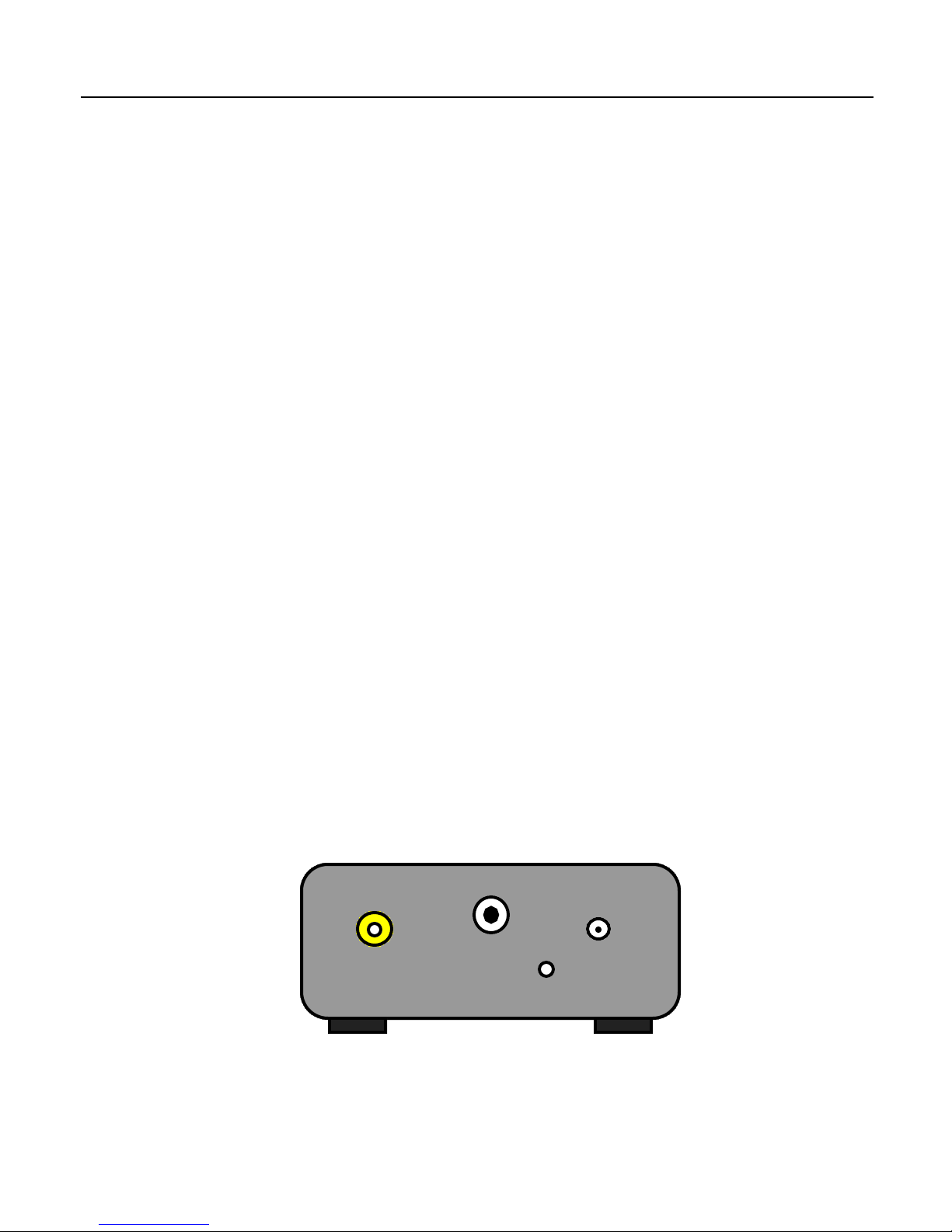
Caution! In the subsequent steps, make sure you are touching one of the outer
metal rings on the phono or RF connectors to discharge any static electricity that
may be present before proceeding. There are static sensitive devices inside the
converter that can be damage if subjected to a static discharge. Failure to follow this
procedure will result in damage to the unit!
Using a small tool such as a paper clip, carefully slide the desired switch to it’s
new position being careful to not put an undue amount of force on the switch that
might damage it or the circuit board. Once the desired switch settings have been
achieved, replace the cover on the unit, and reinstall the two phillips screws.
Position 1,2,3,4 - RF Channel Select:
These switches are used to select the Channel for the RF System the particular
model supports. (currently System A,E,F,L and M) When all four switches are off,
the RF modulator is disabled and put into a low power state. In this mode, the unit
will still output a converted video signal on the composite output connector. When
the switches are set to a valid setting as shown in the Appendix, the given RF
Channel will be output on the RF connector.
Position 5 - RF System Select:
This switch is used to select between two different RF Systems. It is currently
implemented on the SCRF441NM, SCRF343M, SCRF819F and SCRF819L models.
This switch should be OFF for 1946 System M channel assignments, and ON for
1940 System M channel assignments on the SCRF441NM model. This switch should
be OFF for 1937 System M channel assignments, and ON for 1934 System M
channel assignments on the SCRF343M model. This switch should be OFF for
System F or L channel assignments, and ON for System E channel assignments on
the SCRF819F and SCRF819L models respectively. (Note: the System E channels
on these models will operate at a reduced video bandwidth)
Position 6 - Equalization Pulses:
This switch is used to enable/disable equalization pulses in the vertical (frame) sync
for the 819/25i, 455/25i, 405/25i and 343/30i models. This switch has no effect on the
441/30i model as this standard originally included equalization pulses.