AudioArts Engineering R-5 User manual

R-
5
Audio Console
OWNER'SMANUAL
March 1997

AUDIOARTS ENGINEERING
600 Industrial Drive
New Bern, North Carolina 28562
252-638-7000 (Fax 252-637-1285)
Email: email@wheatstone.com
R-5 Audio Console Technical Manual — revised 3/97
©1997 Audioarts®Engineering
(a division of Wheatstone Corporation)
R-5 / June 98

R-5 / Jan 97 Contents - i
Table of Contents
FIRST STEPS / BASIC INFO
Unpacking the Console ................................................................1-2
Mainframe Installation .................................................................1-2
System Ground.............................................................................1-3
Console Power Supply..................................................................1-5
Energizing the Console................................................................1-5
Wiring Overview ............................................................................1-6
Individual Channel I/O Connectors..............................................1-7
Balanced vs Unbalanced Connections.........................................1-8
Wiring Up the Console .................................................................1-9
Set-up and Test.............................................................................1-9
Technical Documentation............................................................1-9
Drawing – Console Controls and I/O Connectors......................1-10
Console System Signal Flow Diagram .......................................1-11
Performance Specifications .......................................................1-12
MONO MIC INPUTS
Overview........................................................................................2-2
Signal Flow Diagram.....................................................................2-2
Controls and Features..................................................................2-3
Mono Mic Input Channel Wiring ..................................................2-4
Audio Connections.......................................................................2-4
Logic and Control Wiring .............................................................2-5
Drawing – Typical Remote Logic/Control Hook-ups ...................2-6
Technical Documentation............................................................2-7
STEREO LINE INPUTS
Overview........................................................................................3-2
Signal Flow Diagram.....................................................................3-2
Controls and Features..................................................................3-3
Stereo Line Input Channel Wiring ...............................................3-4
Audio Connections.......................................................................3-4
Logic and Control Wiring .............................................................3-5
Drawing – Typical Remote Control Hook-ups .............................3-6
Technical Documents ..................................................................3-7
R-5 / Mar 97R-5 / Aug 00

R-5 / Jan 97 Contents - ii
CONTENTS
TELEPHONE INPUT
Overview........................................................................................4-2
Signal Flow Diagram.....................................................................4-2
Controls and Features..................................................................4-3
Wiring – Audio Connections ........................................................4-4
Technical Documentation............................................................4-5
OUTPUTS
Overview........................................................................................5-2
Controls and Features..................................................................5-2
Signal Flow Diagram.....................................................................5-3
Output Wiring ...............................................................................5-4
Technical Documentation............................................................5-5
MONITORS
Overview........................................................................................6-2
Signal Flow Diagram.....................................................................6-3
Controls and Features..................................................................6-4
Monitor Circuit Wiring .................................................................6-5
Audio Connections.......................................................................6-5
Control Wiring ..............................................................................6-6
Technical Documentation............................................................6-7
ACCESSORIES
Overview........................................................................................7-2
Signal Flow Diagram.....................................................................7-2
Controls and Features..................................................................7-3
Accessory Wiring..........................................................................7-4
Tape Remote Switches (Control) .................................................7-4
Line Selector (Audio) ...................................................................7-5
Technical Documentation............................................................7-6

R-5 / Jan 97 Contents - iii
SET-UP AND TEST
Factory Calibration.......................................................................8-2
End-User Set-up and Test ............................................................8-2
Mono Mic Inputs...........................................................................8-2
Stereo Line Inputs........................................................................8-3
Telephone Input ...........................................................................8-5
Outputs .........................................................................................8-6
Monitors (Audio)...........................................................................8-6
Monitors (Control)........................................................................8-7
Talkback .......................................................................................8-8
Tape Remote .................................................................................8-8
Timer.............................................................................................8-8
Line Selector ................................................................................8-9
TECHNICAL DOCUMENTATION
MB-5 mother board schematic.....................................................9-2
MB-5 circuit card dwg.................................................................9-12
MB-5 parts list ............................................................................9-13
OM-5 output board schematic....................................................9-15
OM-5 circuit card dwg ................................................................9-21
OM-5 parts list ............................................................................9-22
SW-R5 circuit card dwg ..............................................................9-25
SW-R5 parts list..........................................................................9-26
Console parts list .......................................................................9-27
Mainframe parts list ...................................................................9-28
APPENDIX
External On Tally Circuit ............................................................ A-2
External Headphone Pad Circuit ................................................ A-2
Monitor Level Settings ................................................................ A-3
Pad Circuit for +4dBu Console Outputs ..................................... A-3
Disabling Phantom Power........................................................... A-4
Hand Crimp Tool Wiring Instructions ........................................ A-5
Extractor Pin Tool Instructions.................................................. A-6
Insert Point Bridging Resistors .................................................. A-7
Denon DN-951 Cd Player Hook-up Diagram ............................... A-8
Studio Dimming Resistors .......................................................... A-9
R-5 / Oct 99

Page 1 - 1
R-5 / Jan 97
FIRST STEPS/BASIC INFO
First Steps/Basic Info
Chapter Contents:
Unpacking the Console ....................................................................... 1-2
Mainframe Installation ........................................................................ 1-2
System Ground.................................................................................... 1-3
Console Power Supply ........................................................................ 1-5
Energizing the Console....................................................................... 1-5
Wiring Overview................................................................................... 1-6
Individual Channel I/O Connectors .................................................... 1-7
Balanced vs Unbalanced Connections................................................ 1-8
Wiring Up the Console ........................................................................ 1-9
Set-up and Test ................................................................................... 1-9
Technical Documentation................................................................... 1-9
Drawing – Console Controls and I/O Connectors............................. 1-10
Console System Signal Flow Diagram .............................................. 1-11
Performance Specifications .............................................................. 1-12
PROGRA
M
AUDITION
10"10"
30.3"
31 3/8"
5"
6 1/2"
21 1/2"
#8
woodscre
w
(t
y
p 4)
R-5 / Aug 00
Page 1 - 2
R-5 / Jan 97
FIRST STEPS/BASIC INFO
UNPACKING THE CONSOLE
The console is shipped as two packages. One (larger) carton contains the
console and technical documentation; the other (smaller) contains the
rackmount power supply, connecting cable, and connector kit.
MAINFRAME INSTALLATION
DO NOT CONNECT THE R-5 CONSOLE TO ITS POWER SUPPLY, AND DO
NOT CONNECT THE POWER SUPPLY TO THE AC POWER LINE UNTIL
INSTRUCTED TO DO SO.
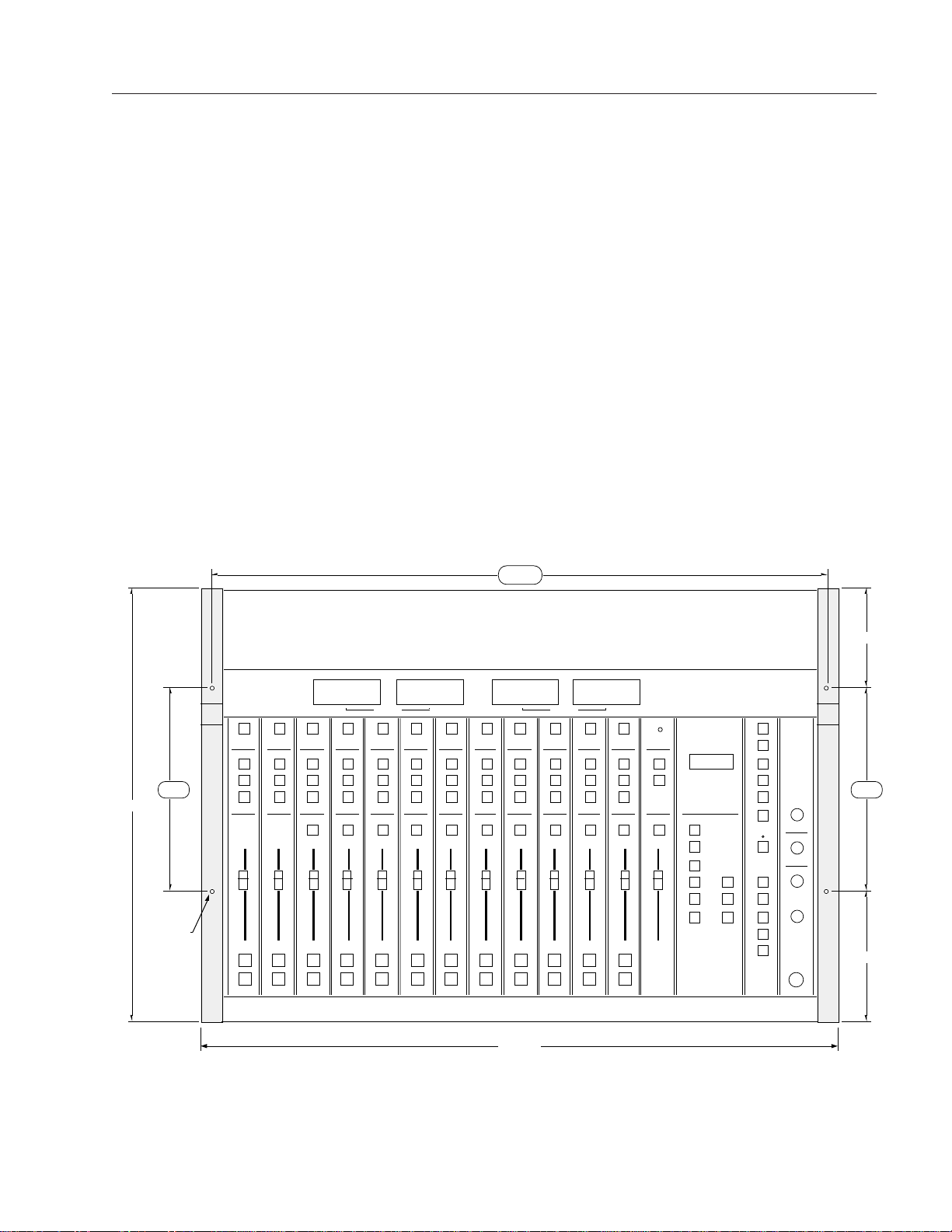
It is not necessary to prepare the counter by making a cutout, since the
R-5 is mounted above the counter top. If you will be securing the console
to a counter top, you will need to drill mounting holes for four #8
woodscrews as shown in the drawing below.
PROGRAM AUDITIO
N
10"10"
30.3"
31 3/8"
5"
6 1/2"
21 1/2"
#8
woodscrew
(t
y
p 4)
Pre-drillfor#8woodscrews—doNOTuselargerdiameterscrews;theymaysplittheconsolewood!
Drill COUNTERTOP with .173" diameter (#17 drill) clear holes. Pre-drill CONSOLE WOODEN
ENDPIECES from below with .136" diameter (#29 drill) tap holes. Use hole locations as shown.
Attach the console mainframe to the counter top by screwing up through
the counter into the tap holes you have drilled into the bottom of the
mainframe's left and right wooden end pieces (two per side).
R-5 / Sep 02

Page 1 - 3
R-5 / Jan 97
FIRST STEPS/BASIC INFO
The first step is to ground the console.
SYSTEM GROUND
While console power supply common, audio common, and the
mainframe chassis are connected together at the R-5 mainframe, they
are not connected to electrical ground and the chassis of the power
supply.Safetyrequirementsdictate thatapositiveconnectionfrom the
console mainframe to electrical ground be made in the completed
installation; audio requirements also dictate this same connection—
use the two grounding lugs on the connector surface area of the
mainframe(underneaththehingedmeterbridge)toestablishyoursystem
ground (see left AUD VU meter area on drawing on page 1-1).
The system ground serves two important purposes:
(1) Provides a zero signal reference point for the entire audio system;
(2) Assures safety from electrical shock.
There exist two terms that one encounters in a discussion of ground:
(A) EARTH GROUND, which is usually a heavy copper rod driven
into the soil adjacent to the building (around 6 feet down) or
a connection to the copper water pipes leading into the
building. Either is acceptable (unless, of course, the water
pipes are plastic).
(B) THE POWER COMPANY EARTH CONDUCTOR that enters the
buildingatthepower line breaker box; this conductorshould
be (and is often by code) tied to the above-mentioned earth
ground at one point. This point is the SYSTEM EARTH
GROUND.
TIE THE CONSOLE GROUND LUG TERMINALS TO THE SYSTEM
EARTH GROUND. TIE EVERY PIECE OF EQUIPMENT IN THE ENTIRE
AUDIO SYSTEM TO THE CONSOLE'S GROUND LUG TERMINALS. If the
system earth ground point is inaccessible, tie the console ground
terminalstothepowercompanyearthconductoratthemainbreakerbox
(see drawing "Typical Grounding Scheme" on page 1-4).
Each piece of equipment should be connected by its own ground wire
(usually the round third pin on the AC cord). This means that every AC
outlet must have a separate conductor run to the console ground lug
terminals;theoutletscannotbedaisy-chainedasisnormallyencountered
in commercial and residential AC systems. Any equipment not supplied
with 3-wire AC cables must have individual ground wires (16 gauge or
larger) connected to their chassis grounds and then run to the console
ground lug terminals.
Page 1 - 4
R-5 / Jan 97
FIRST STEPS/BASIC INFO
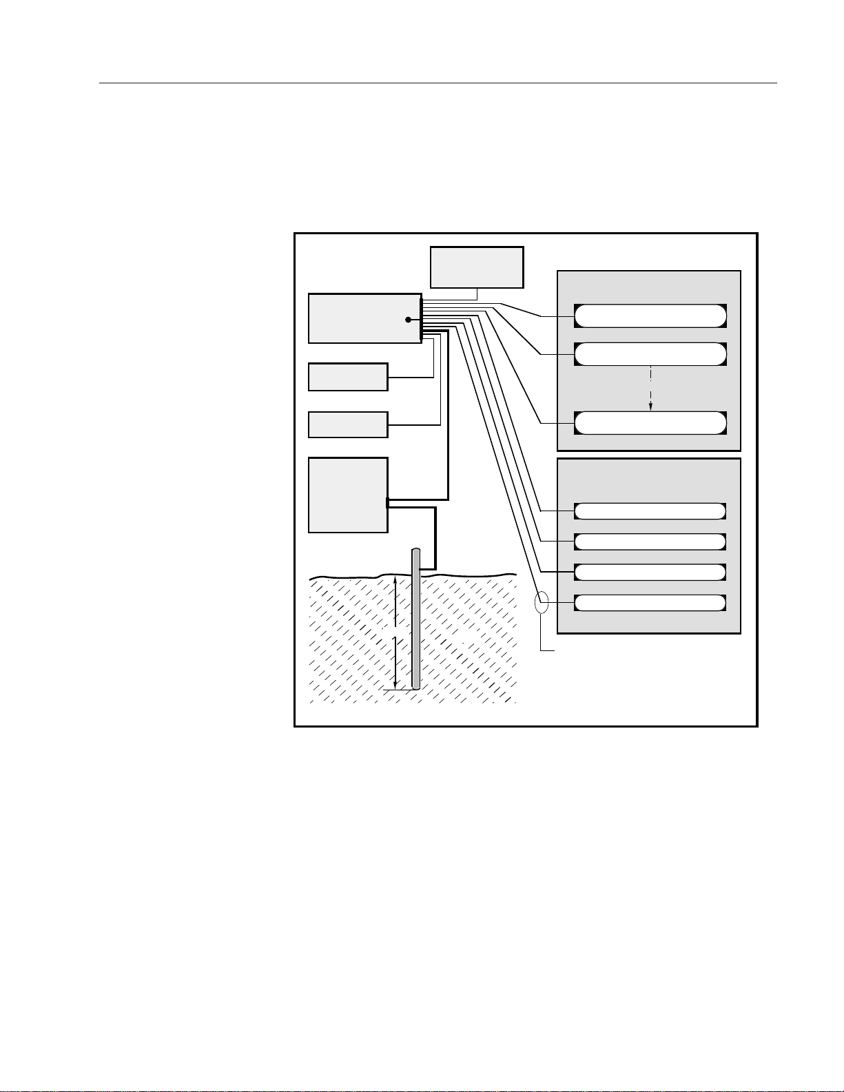
Tie the console's ground lug
terminals to the system earth
ground. Tie every piece of
equipment in the entire audio
system to the console ground
lug terminals.
CONSOLE
2-TRACK
MULTI-TRACK
AC BREAKER
BOX
DEVICE 1
DEVICE 2
DEVICE N
CONSOLE POWER SUPPLY
CONTROL ROOM POWER AMP
STUDIO POWER AMP
OTHER
POWER COMPANY
EARTH GROUND
HEAVY
(#4 or #6)
COPPER
WIRE
HIGH POWER
EQUIPMENT RACK
COPPER ROD
SOIL
3-wire ground or separate wire run from chassis
EFFECTS RACK
MIC PANEL
GND
TYPICAL SYSTEM
GROUNDING SCHEME
etc.
3–5 ft.
Further Grounding Details
Check all equipment to be absolutely certain that each unit is power
transformer isolated from the AC mains to prevent safety hazards.
It is assumed that in each piece of audio equipment the audio ground
and the chassis are tied together at some point. Any piece of equipment
lackingagroundedchassisislikelytobepronetointerferenceproblems.
Locate all unbalanced audio equipment in the same rack if possible, to
minimize chassis ground potential differences. It may also be helpful to
insulate each piece of unbalanced equipment from it’s mounting rails in
therack bymeans of nylon 10-32 screws and insulating washers between
rails and faceplates.
As a rule of thumb, consumer
units (low level, –10dBu,
unbalanced) usually utilize RCA
jacks and two conductor wiring
connections; professional level
equipment (+4dBu, balanced)
generally uses three-conductor
XLR connectors.

Page 1 - 5
R-5 / Jan 97
FIRST STEPS/BASIC INFO
The next step is to install the rackmount power supply.
THE CONSOLE POWER SUPPLY
The R-5 console uses a separate rackmount power supply unit. The
power supply should be mounted in an adjacent equipment rack within
fifteen feet (but no closer than 3 feet) of the console. It should be
mounted in a rack space (it requires two rack spaces or 3-1/2") where
properaircirculationispossible.Avoidlocatinganyhighgainequipment
(suchasphonopreamps,taperecorders,etc.)toonearthepowersupply,
to avoid magnetic interference into that equipment.
Once the supply is mounted, connect the linking power cable at the
console end; the connector is a 6-pin plug that mates with a matching
socket("DCIN")mountedontheconsoleconnectorareaunderneaththe
righthand end of the hinged meterbridge (see drawing page 1-10).
Connect the other end of the cable to the rear of the rackmounted power
supply.
The power supply is fitted with a 3-wire grounded AC cord that should
be plugged into a “clean” AC power source. That is, an AC source that
feedsonlythecontrolroomaudiogear. Thissourceshouldbeaseparate
feed from those powering lighting, air-conditioning, or any other non-
audio machinery. The third pin ground wire of the AC source should be
tied to the system earth ground point (see “System Ground” section).
Note that while the AC power cord ground wire terminates at the power
supply chassis, it does NOT connect to the R-5 console common; the
console itself must be grounded separately. (See previous section:
“System Ground”.)
ENERGIZING THE CONSOLE
Assuming the console mainframe is properly installed and grounded,
and its power supply correctly rackmounted and connected to the
console,youmaynowenergizetherackmountpowersupplybyplugging
it into the AC mains.
The four LEDs on the power supply front panel should light up to
indicate the presence of their respective voltages. The console's VU
meters and timer display will illuminate. All other switches should
alternateonandoffwhenpressedinsuccession.(NoteCUEswitcheswill
de-activate when an associated line input red channel ON switch is
pressed. Amber channel OFF switches should deactivate ON switches
when pressed.
Once you have verified proper power-up, unplug the rackmount
power supply to de-energize the console.
You are now ready to proceed with audio and control wiring. First,
however, you should familiarize yourself with the R-5 wiring system
and supplied tools (next section).
The power feed recommended
in the text is often installed and
referred to in studios as an “iso-
lated AC ground” outlet.
It is usually orange in color.
Table of contents
Other AudioArts Engineering Recording Equipment manuals

AudioArts Engineering
AudioArts Engineering D-70 User manual

AudioArts Engineering
AudioArts Engineering D-76 User manual

AudioArts Engineering
AudioArts Engineering R-60 User manual

AudioArts Engineering
AudioArts Engineering R-55 User manual

AudioArts Engineering
AudioArts Engineering D-16 User manual

AudioArts Engineering
AudioArts Engineering D-75 User manual


