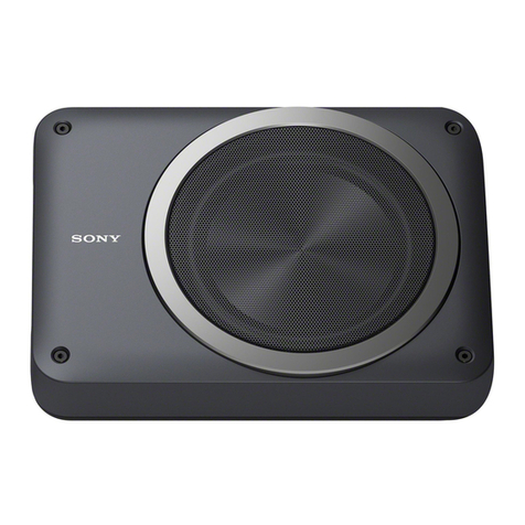
AUDAC SX408A Installation and operating instructions

PROFESSIONAL AUDIO EQUIPMENT
SX408A Active Subwoofer System
User Manual &
Installation Guide
SX408A
AUDAC

AUDAC PROFESSIONAL AUDIO EQUIPMENT
User Manual & Installation Guide
AUDAC
http://www.audac.eu

2
INTRODUCTION..................................................................................................................................................................................................................... 3
ENVIRONMENT ...................................................................................................................................................................................................................... 4
SAFETY REQUIREMENTS ................................................................................................................................................................................................... 5
CAUTION –SERVICING...................................................................................................................................................................................................... 5
OVERVIEW REAR PANEL ................................................................................................................................................................................................... 6
REAR PANEL DESCRIPTION .............................................................................................................................................................................................. 7
AMPLIFIER INDICATOR LED’S......................................................................................................................................................................................... 7
RJ45 REMOTE CONTROL CONNECTION ........................................................................................................................................................................ 7
SATELLITE VOLUME CONTROL ...................................................................................................................................................................................... 8
SUBWOOFER VOLUME CONTROL .................................................................................................................................................................................. 8
BALANCED INPUT CONNECTIONS ................................................................................................................................................................................. 8
SATELLITE OUTPUT CONNECTIONS.............................................................................................................................................................................. 9
POWER SWITCH ................................................................................................................................................................................................................. 10
MAINS POWER CONNECTION ........................................................................................................................................................................................ 10
BLOCK DIAGRAM ............................................................................................................................................................................................................... 11
SX408A SET SOLUTIONS.................................................................................................................................................................................................... 12
FESTA 400 ............................................................................................................................................................................................................................ 12
CONGRESS 400 ................................................................................................................................................................................................................... 13
ADDITIONAL INFORMATION.......................................................................................................................................................................................... 14
PERSONAL NOTES............................................................................................................................................................................................................... 15
Index

3
Introduction
This section briefly describes the possibilities of the SX408A active subwoofer system.
he SX408A is an active powerful tandem ported 150W subwoofer with a special
constructed 8" driver that is capable of producing an incredibly powerful and clear
bass sound. It’s frequency response is as low as 37 Hz at -10 dB, and the frequency
characteristic is very flat from 37 Hz to 120 Hz. This way, the sound coming from
this piece of equipment is absolutely magnificent.
It contains an integrated class H amplifier, which ensures a high efficiency level with very low
distortion. This amplifier delivers an output power of 100 Watt to the subwoofer. Besides
this, it also contains an active crossover network with a frequency of 120 Hz, and two output
channels for powering satellite loudspeakers.
The two amplified satellite outputs deliver a maximum power of 2 x 100 Watt at 8 Ohm or 2
x 160 Watt at 4 Ohm. The minimum load is 4 Ohm.
For protection reasons, a built-in limiter is provided to limit the input signal when necessary.
This limiter consists of three separate stages, one for every channel. This ensures the best
sound quality with the least distortion for optimal performance. Power, Signal and Clip
LED’s monitor the proper working of the integrated amplifier.
Besides the high efficiency of the class H amplifier, the SX408A also contains an automatic
power on/off circuit to ensure the highest energy-efficiency. The volume of the Sub and
satellite channels is individually controllable at the back of the subwoofer with two
potentiometers, and the general volume can be controlled by an external volume control or
wall panel, by connecting it to the built-in RJ45 connector.
This all makes the SX408A a simple but complete solution for a wide variation of fixed audio
installations. The balanced input connections are just as the satellite speaker output
connections made with euro block terminal connectors. There is the possibility to connect
two satellite speakers with an impedance of 8 Ohm on each channel.
T

4
Environment
Do not place this unit in an enclosed environment such as a bookshelf or closet. Ensure
that there is adequate ventilation to cool the unit.
Do not place the unit in environments which contain high levels of dust, heat, moisture or
vibration.
Do not use the unit near water or other liquids. Make sure no water or other liquids can be
spilled, dripped or splashed on the unit.
This unit was developed for indoor use only. Do not use it outdoors.
Do not place objects on top of the unit.
Chapte
r
1

5
Safety Requirements
Always handle the unit with care.
Only use a grounded socket outlet and a power cord with grounding plug to plug in the
unit.
This unit is not a toy. It should not be operated by children.
Do not stick objects through the openings.
Do not open the unit (risk for electrical shock).
CAUTION – SERVICING
This unit contains no user serviceable parts. Refer all servicing to qualified
service personnel. Do not perform any servicing unless you are qualified to do
so.
Note
This product conforms to the following European Standards: EN 50081-1: 1992, EN
50082-1: 1992, EN 60065: 19

6
Overview rear panel
Chapte
r
2
2. RJ45 Remote control connection
1. Amplifier indicator LED’s
3. Satellite outputs volume control
4. Subwoofer volume control
5. Balanced input connections
6. Satellite output connections
7. POWER switch
8. MAINS power connection

7
Rear panel description
1) Amplifier indicator LED’s
There three LED’s monitor the proper working if the integrated amplifier.
-Power LED:
When the power switch is turned on, and the amplifiers mains power connection is
connected to an AC power supply, this indicator will light up to let you know that the
system is ready for operation.
When the LED lights up green, the amplifier is switched on, and ready to rock and roll.
When the LED lights up orange, the amplifier is in stand-by mode. This means that there
is no input signal present. The amplifier will switch automatically ON when an input signal
is applied.
-Signal LED:
This LED illuminates whenever there is a signal present at the input connectors.
-Clip LED:
The SX408A has a built-in limiter that prevents the outputs from overdriving. When the
Clip LED lights up frequently, the level must be reduced, because the maximum power is
reached.
2) RJ45 remote control connection
On this RJ45 connection, an optional VC4008 volume controller can be connected through UTP
cabling. With this volume controller, the general volume of the integrated amplifier can be set, of
both the satellite and subwoofer channels.
UTP CAT5 Cabling

8
3) Satellite volume control
With this dial, the output level of the satellite channels can be set.
The attenuation of the signal can be set between 0dB and -50dB by rotating the dial.
4) Subwoofer volume control
With this dial, the output level of the subwoofer channel can be set.
The attenuation of the signal can be set between 0dB and -50dB by rotating the dial.
It is important to find a good balance between the high and low tones by using
the Satellite and Subwoofer volume controls. The perfect balance will depend
on the application and on the location. For vocal applications there will be a
different ideal balance than for music applications.
5) Balanced input connections
These euro terminal input connections accept a balanced line level input signal. An input signal can
be fed from a mixing console or other signal source.
To connect the system to a music source with balanced XLR output connectors, or with
unbalanced RCA/Cinch output connectors, the connection cables should be connected according
to the following schematics:

9
Balanced:
Unbalanced:
Red
Shield
Tip
Sleeve
6) Satellite output connections
On these euro terminal output connections is the amplified output signal present with a frequency
above 120Hz. Connect these to the satellite speakers.
A total of 4 speakers with an impedance of 8 Ohm can be connected to these output connections.
The total impedance load should not be lower than 4 Ohms.
Table of contents
Other AUDAC Subwoofer manuals