
AU Tool BT280 User manual

R
Intelligent Electrical System Circuit Tester
Intelligent Electrical System Circuit Tester
User’s Manual
BT280

TABLE OF CONTENTS
1. About BT280......................................................................................... 2
1.1 Overview.................................................................................................. 3
1.2 Specifications and Parameters............................................................ 4
1.3 Packing List............................................................................................ 4
1.4 Power Supply Connectio....................................................................... 5
1.5 Key Button Operation............................................................................ 5
1.6 Circuit Breaker Protection.................................................................... 6
2. Working Mode....................................................................................... 7
2.1 Smart Test............................................................................................... 7
2.2 Multimeter Mode.................................................................................... 8
2.3 Oscilloscope Mode................................................................................ 9
2.4 Relay Test..............................................................................................10
2.5 Component Activation......................................................................... 12
2.6 0-5V Power Supply............................................................................. 14
2.7 Fuel Injector Test................................................................................. 15
2.8 Positive/Negative Test........................................................................ 16
2.9 Setting................................................................................................... 17
2.10 Online Update....................................................................................... 18
3.Test Applications................................................................................. 19
3.1 Continuity Test......................................................................................19
3.2 Signal Circuit Test................................................................................20
3.3 Activating Components in You Hand.................................................21
3.4 Activating Components in Vehicle......................................................22
3.5 Activating Components W/Ground.....................................................24
3.6 Checking for Bad Ground Contacts...................................................25
3.7 Following&Locating Short Circuits.....................................................26
3.8 Trailer Lights and Connection Test................................................... 27
4.Warranty and Service.......................................................................... 28
4.1 One-Year Warranty............................................................................. 28
4.2 Service Process.................................................................................... 28

To prevent personal injury or damage to vehicles and / or the scan tool,
read this user's manual first carefully and observe the following safety
precautions at a minimum whenever working on a vehicle:
Always perform automotive testing in a safe Environment.
Do not attempt to operate or observe the tool while driving a vehicle,
Operating or observing te tool will cause driver distraction and could
cause a fatal accident.
Wear safety eye protection that meets ANSI standards.
Keep clothing, hair, hands , tools , test equipment, etc. Away from all
moving or hot engine parts.
Operate the vehicle in a well-ventilated work area. Exhaust gases are
poisonous.
Put blocks in front of the drive wheels and never leave the vehicle
unattended while running tests.
Use extreme caution when working around the ignition coil, distributor
cap, ignition wires and spark plugs. These components create
hazardous voltages when the engine is running.
Put the transmission in P (for A/T) or N(M/T) and make sure the
parking brake is engaged.
Keep a fire extinguisher suitable for gasoline /chemical / electrical
fires nearby.
Don't connect or disconnect any test equipment while the ignition is
ON or the engine is running.
Keep the scan tool dry, clean free from oil/ water or grease. Use a
mild detergent on a clean cloth to clean the outside of the scan tool
when necessary.
Our company is not responsible for any damage caused by
unintentional or deliberate misuse of our products or tools
Safety Precautions and Warnings
- 1 -

About BT280
1. About BT280
The bt280 is the newest generation intelligent Electrical System Cir-
cuit Tester with 2.4 inch large size LCD screen display. It is dedicated to
test all 9V-30V vehicle electrical systems. BT280 is Convenient, Fast and
Intelligent !
Smart Test - Auto Detect Volts and Ohms
Multimeter Mode(Voltage,Resistance,Diode,Open&Short,
Current, Frequency)
Relay Test Diode Test Oscilloscope Test
0-5V Power Supply Component Activation
Positive&Negative Test Multi - Languages
Circuit Breaker Protection(Current Adjustable)
Screen Background Changeable Online update
- 2 -

4
3
5
7
8
10
9
6
11
1
2
- 3 -
1.1 Overview
① Probe Tip - contact the circuit or component for testing.
② Front LED light- Used for lighting in dark working areas or when
working at night.
③ Red/green LED indicator- Positive and Negative indicator light.
④ LCD screen- Display test results.
⑤ Key Button Operation- 5 Keys Navigating for fast operation.
⑥ Speaker- Buzzer for warning or remind.
⑦ Auxiliary ground lead- Auxiliary clip of ground lead
(probe negative).
⑧ Power Connector – Connect the battery clip to the car battery
and extension cable.
⑨ Relay Test Port- Connect the relay test cable
⑩ HOOK- Hook the probe in a suitable place to avoid broken and
Convenient in use.
11 USB Port- Update by connect PC with USB cable to probe

1.2 Specifications and Parameters
① LCD: (320*240 DPI) TFT color display
② Working temperature: 0-60°C (32-140 F°)
③ Storage temperature: 40-70°C (-40-185 F°)
④ External power supply: 12V or 24V Powered by battery
⑤ Minimum working voltage: 9V
⑥ Maximum working voltage: 30V
⑦ Maximum measuring voltage: 150V
⑧ Minimum measuring voltage: 0.1V
⑨ Resistance measurement range: 1 ohm~200K ohm
⑩ Current measuring range: 0~18A
Maximum continuous current: 18A
1.3 Packing List
11
BT280 Unit with 6 meters test line
Solid copper test probe tip
Extension connection line
Alligator battery clip
Relay test line
Probe adapter
25Amp fuse
User manual
ABS Toolbox
- 4 -

- 5 -
1.4 Power Supply Connection
The Probe is powered by the vehicle battery. Connect the RED clip to
the positive pole of the battery, and the BLACK clip to the negative pole
of the battery. The machine will automatically start to enter the working
interface, The front LED light will illuminate the test area, which is conve-
nient for operation in the dark area.
1.5 KEY Button Operation
The Probe equipped with multi-function button adopts the latest
scientific design. There are 5 physical buttons “Left ", “Right ", “Up ",
“Down " and “OK".
- 6 -
* In different functional interfaces, the key functions performed are not
exactly the same.
Left key- navigation key or exit key
Right key- navigation key
Up key- navigation key or voltage output, numerical adjustment
Down button-navigation button or voltage output, numerical
adjustment
OK- Confirm key
1.6 Circuit Breaker Protection
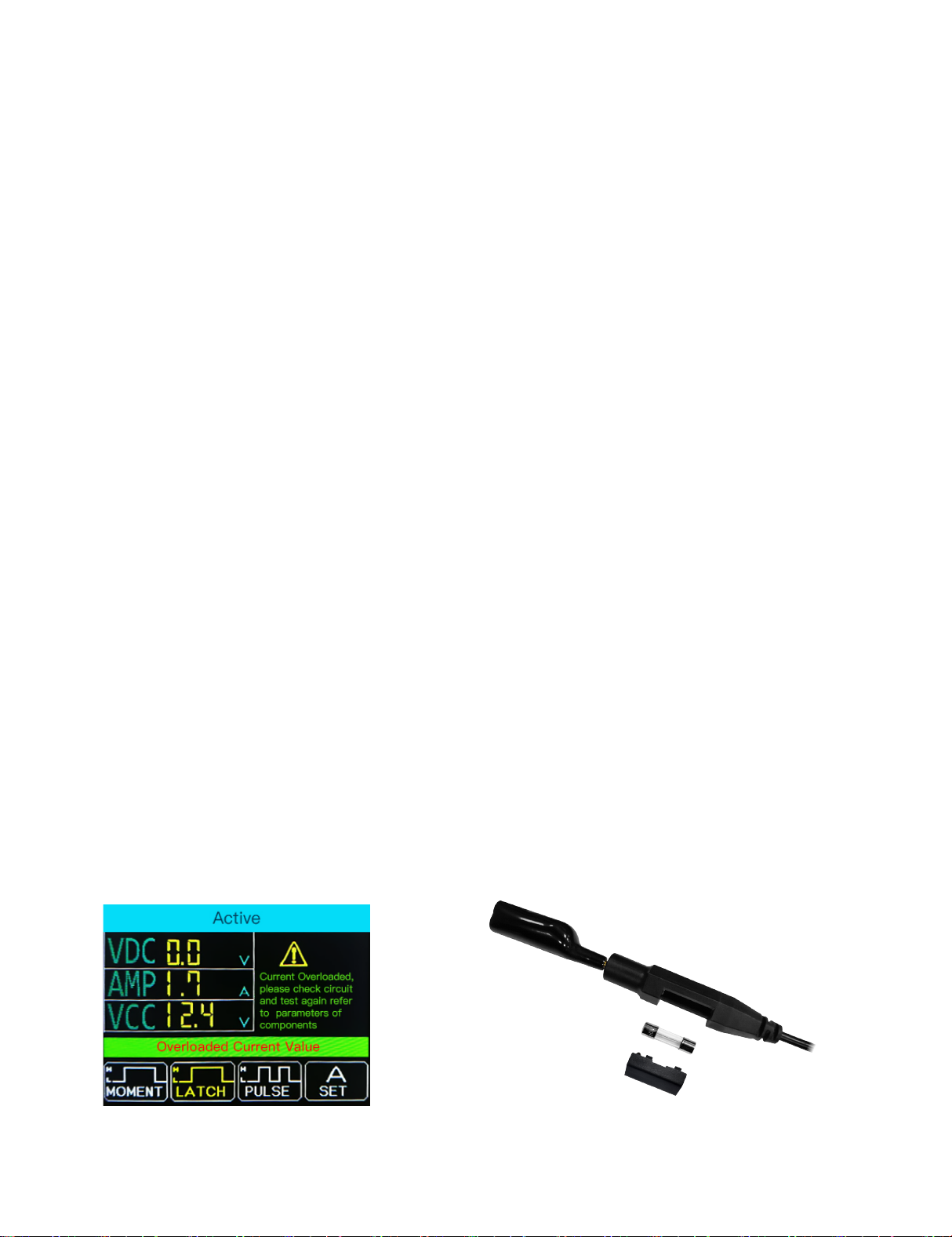
1. Short-Circuit Automatic Protection - if current overloaded, its internal
circuit breaker system will automatically tip for protection. The circuit
breaker monitors this tool at all times. As an essential safety measure to
prevent overload, it is a very practical function.
2. Fuse Protection- Equipped with a 25amp fuse in the auxiliary
grounding lead, which can be protected when the device is
short-circuited or overloaded.
* Do not use the BT280 probe to test the voltage of the household AC
Power (such as 110V, 220V plug), , it may cause serious injury and
property damage for improperly operation.

Working Mode
2.Working Mode
This probe adopts a 2.4-inch large color screen and 9-grid interface
design, with clear display, simple operation and quick in use. You can
select working mode through the navigation buttons and press OK to
enter.
- 7 -
2.1 Smart Test
The main test functions of this mode: voltage test , resistance test, Posi-
tive/negative test. ( display as VDC, OHM). It is mainly used for quick test
without switching between different test modes. Automatically recognize
the measured signal and display values of voltage or OHMs.
2.1.1 Voltage Test Result
How to use: When the probe clip (auxiliary ground lead) is connected to
the ground wire, the probe will automatically enter the voltage display
mode when a voltage signal detected on the probe Tip, it will display the
test voltage.

- 8 -
As shown in the figure, “BATT” means that the battery supply voltage is
9.9V, and “VDC” is the current test DC voltage value 10.0V.
2.1.2 Resistance Test Result
How to use: When the probe clip (auxiliary ground lead) is connected to an
electrical circuit of resistance and the probe Tip is connected to the other
end of the resistance, the probe will automatically enter into the resis-
tance display mode and display the resistance values.
2.1.3 Postive/Negative Test
When the probe detected voltage deviation of +_0.8v from the power
supply, the RED LED lights ON, meanwhile it displays the voltage values,
and the speaker sounds regularly. When Probe detected the negative
signal of the power supply, the GREEN LED lights ON, and the speaker
sounds regularly. (Speaker Enable/Disable in Setting)
2.2 Multimeter Mode
As shown in the figure: “BATT” means that the battery supply voltage is
9.9V, and “OHM” is the current test resistance value 0.0 Ω.
Table of contents
Popular Circuit Tester manuals by other brands


OEM
OEM 24366 Operating instructions and parts manual

JDS Uniphase
JDS Uniphase IP Video Test Option HST-3000 user guide

Sealey
Sealey FF400 instructions

PEAKMETER
PEAKMETER PM8908C manual

YOKOGAWA
YOKOGAWA CL345 user manual

ABB
ABB SACE Emax 2 Installation, operation and maintenance instructions for the installer and the user


