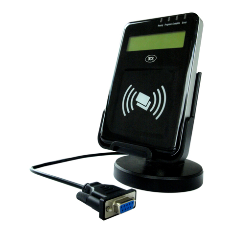
ASIS Technologies R380 Series User manual

1
R380 Series Reader
User Manual
Document History
Description
Aug 2017 Revision 1
Federal Communication Commission Interference Statement
This equipment has been tested and found to comply with the limits for a Class B digital device, pursuant to
Part 15 of the FCC Rules. These limits are designed to provide reasonable protection against harmful
interference in a residential installation.
This equipment generates uses and can radiate radio frequency energy and, if not installed and used in
accordance with the instructions, may cause harmful interference to radio communications. However, there is
no guarantee that interference will not occur in a particular installation. If this equipment does cause harmful
interference to radio or television reception, which can be determined by turning the equipment off and on, the
user is encouraged to try to correct the interference by one of the following measures:
. Reorient or relocate the receiving antenna.
. Increase the separation between the equipment and receiver.
. Connect the equipment into an outlet on a circuit different from that to which the receiver is connected.
. Consult the dealer or an experienced radio/TV technician for help.
FCC Caution: To assure continued compliance, any changes or modifications not expressly approved by the
party responsible for compliance could void the user's authority to operate this equipment. (Example - use
only shielded interface cables when connecting to computer or peripheral devices).
This device complies with Part 15 of the FCC Rules. Operation is subject to the following two conditions:
(1) This device may not cause harmful interference, and (2) This device must accept any interference
received, including interference that may cause undesired operation.

2
Contents
Document History ...................................................................................................................................... 1
Federal Communication Commission Interference Statement.................................................................. 1
1.1
R380 Series NFC Reader Overview ................................................................................ 2
1.2
Reader Wiring and Color Code........................................................................................ 3
1.3
DIP Switch Setting (See table 3,4 for detail).................................................................... 3
1.4
Dimension ........................................................................................................................ 4
1.5
Installation And Mounting Instruction............................................................................... 5
1.6
Operation Guide............................................................................................................... 6
1.7
R380 LCD screen message............................................................................................. 7
1.8
Package List – R380 Reader ......................................................................................... 12
1.9
Product Electrical Specification...................................................................................... 13
1.1 R380 Series NFC Reader Overview
The R380 Series Reader is a weather proof, high heat ABS NFC card
reader. The R380 Series NFC reader can read a wide range of
contactless smart card covering single size UID card to double size
UID card. Card ID data can be output via industry standard Wiegand
or Asis Proprietary RS485.

3
1.2
Reader Wiring and Color Code
Terminal Point
Label
Description Recommended Cable
Color
Dev+ RS485+ Blue
Dev- RS485- Grey
+V +12VDC Red
GND DC Ground Black
D0 Wiegand Data 0 Green
D1 Wiegand Data 1 White
ERL Red LED Brown
OKL Green LED Orange
BUZ Buzzer Yellow
Hold Purple
Table 2 Wiring and Cable Color code
1.3 DIP Switch Setting (See table 3,4 for detail)
BIT 1 2 3 4 5 6 7 8
Function
(RS485) ADDRESS BIT MODE and Data Out BIT TEST BIT
bit 0 bit 1 bit 2 bit 3 Off-Wiegand
On- RS485
Off- 8 byte
On -4 byte
Off – CSN
On - CAN
Off – Run
On - Testing
Function
(Wiegand)
Card format Setting
Table 3 Dip Switch function explain

4
BIT
Reader Hex
address
1 2 3 4 5 ~ 8
Function
(RS485)
BIT
Address
1 80 Off Off Off Off Refer to
above
table
2 81 On Off Off Off
3 82 Off On Off Off
4 83 On On Off Off
5 84 Off Off On Off
6 85 On Off On Off
7 86 Off On On Off
8 87 On On On Off
Table 4 RS485 Readers Address Dip Switch Setting
1.4 Dimension
WebENTRA
76.00mm.
135.00mm.
FRONT SIDE
21.00mm.
Reader Module Dime sio

5
1.5 Installation And Mounting Instruction
Remove Bottom Screw
Ply open the front cover
using flat head screw driver
remove the front of the unit.
Remove the front of unit
Mark out reader base
(reader wire pigtail) and
(wall mounting hole) drill
hole on the wall for
mounting reader.
Half tighten wall mount
screw.
Terminate reader pigtail
cable to cable from
controller. Tighten wall
mount screw

6
Reinsert reader front to
base by set the bottom.
Align reader pigtail cable
accordingly. Push to front
top to snap into the base.
Tighten bottom screw
1.6 Operation Guide
Keeping the card in parallel to the R380 reader a maximum read range
can be obtained. The Reader will still be able to read Card when the
card is presented at an angle but this will result in the reducing of read
range.
Card and PIN operation
a) In Card & Pin mode LCD screen prompt to Enter Pin, enter PIN
follows by “#” key
b) Key in PIN + 1 for PIN DURESS (Example PIN is 1234, for duress
activation, key pin 1235) Note that the maximum PIN is up to 6 digit.

7
1.7 R380 LCD screen message
Reader Ready Screen Reader Comm Fail
Access Granted Card Flash Access Denied

8
Access Granted Card Invalid
Card Read Comm Fail Fire

9
DOTL Door Force Open
Pre Alarm Box Tamper

10
Reader Tamper
Always Lock Always Unlock
Table of contents
Other ASIS Technologies Card Reader manuals