Asco 230 Series User manual

SERIES 230 Automatic Transfer Switch
C2000 Intelligent Controller User Manual
Document Version V1.2
Archive Date September 26, 2012
BOM Code 1012586
Emerson Network Power provides customers with technical support. Users may contact the nearest
Emerson Network Power sales office or service center.
Copyright © 2012 by Emerson Network Power Co., Ltd.
All rights reserved. The contents in this document are subject to change without any prior notice.
Emerson Network Power Co., Ltd.
Address: No.1 Kefa Rd., Science & Industry Park, Nanshan District 518057, Shenzhen China
Website: www.emersonnetworkpower.com
Customer Service Hotline: 4008-876-510
E-mail: [email protected]


Contents
Chapter 1 Overview ............................................................................................................................................................ 1
1.1 Appearance .......................................................................................................................................................... 1
1.2 Functions and Features ........................................................................................................................................ 1
1. Technical Parameters ........................................................................................................................................... 2
1.4 Accessory Information ..........................................................................................................................................
1.5 C2000 Controller Dimensions ............................................................................................................................... 4
Chapter 2 Installation and Wiring ........................................................................................................................................ 5
2.1 Installation ............................................................................................................................................................. 6
2.1.2 Controller Installation in Cabinet Panel ...................................................................................................... 7
2.1. Controller Wiring ........................................................................................................................................ 8
2.2 Controller Interface and Connection Cable Information ...................................................................................... 10
2.2.1 Controller Interface .................................................................................................................................. 10
2.2.2 Connection Cable Information ................................................................................................................. 1
Chapter Operation .......................................................................................................................................................... 14
.1 Operation Panel .................................................................................................................................................. 14
.2 Display Screen .................................................................................................................................................... 15
.2.1 Start Page ................................................................................................................................................ 15
.2.2 LCD Display Contrast Adjustment ........................................................................................................... 16
.2. Interface of Switch Transferring Status .................................................................................................... 16
.2.4 Password ................................................................................................................................................. 17
.2.5 Parameter Setting Menu .......................................................................................................................... 17
Chapter 4 Maintenance and Troubleshooting ................................................................................................................... 24
4.1 Start Up / Function Test ...................................................................................................................................... 24
4.2 Maintenance ....................................................................................................................................................... 24
4. Common Troubleshooting ................................................................................................................................... 24
Appendix 1 Log Description .............................................................................................................................................. 25
Appendix 2 Battery Replacement ...................................................................................................................................... 26
Appendix Power Properties ............................................................................................................................................ 27


Chapter 1 Overview 1
ASCO Series 2 0 Automatic Transfer Switch C2000 Intelligent Controller User Manual
Chapter 1 verview
ASCO Series 2 0 C2000 Intelligent Controller (hereinafter referred to as Controller) is used to control the Series 2 0
transfer switch. The Controller is designed to control two sources. When either source has over voltage, low voltage,
failure, or abnormal frequency, the Controller will instruct the transfer switch to transfer to a better source or transfer to
the center-off position in order to protect the load.
Key Controller features include AC voltage & frequency signal acquisition, control signal input/output, user interface
(LCD display, LED indicator lights and keys), and RS485 communication (supporting MODBUS protocol).
The Controller appearance, functions and features, technical parameters, accessory configurations, and size of the
Controller will be described in this chapter.
1.1 Appearance
Please refer to Fig 1-1 for the appearance of the Controller.
Power
Connector
Signal
Connector
User ConnectorCorner Snap
ControllerController Operation Panel
Figure 1-1 Controller Appearance
1.2 Functions and Features
Detecting and displaying the voltages, frequencies and three-phase imbalance of two AC input sources, alarming
and displaying when failures occur as overvoltage, under-voltage, over frequency and under frequency, etc.
Multiple operating modes: Automatic (Source I Priority, No Source Priority), Remote Control, and Manual.
Center-off position delay and Center-off position protection modes.
Center-off position delay mode
When the transfer switch transfers the load from one source to another source, the transfer switch should stay in
center-off position for a period of time.
This time can be settable by user depending on the load characteristics. The default setting is 0 seconds, in
order to consume the load inertia and protect the load from getting damaged by the inrush current when the load
transfers from one source to another source.
Center-off position protection mode:
When there are abnormalities with both Source I and Source II, the transfer switch will transfer the load to the
center-off position to protect the load from getting damaged.
Built in abnormal transfer diagnosis capabilities in order to protect the transfer switch.
Utilizes high frequency switch power in order to have a wide input voltage range (80Vac~480Vac).
Capable of operating with DC 24V.
Many settable options, including over/under voltage, over/under frequency for both sources, and switching time
delays.
Configurable DI / DO Ports

2 Chapter 1 Overview
Series 2 0 Automatic Transfer Switch C2000 Intelligent Controller User Manual
RS485 with MODBUS communications protocol
Up to 100 event log recording capability. Log is saved in the event of a power loss.
1. Technical Parameters
Application condition requirements of C2000 Controller as shown in Table 1-1.
Table 1-1 Application Conditions of C2000
Requirement Condition Standards
Temperature
Operating Temperature -20℃~+60℃
IEC61800-1 Storage Temperature -40℃~+70℃
Temperature Change 5℃/min
Humidity 95%, No condensation IEC60721- - K
Altitude 2000m or less IEC60721- - K
Vibration 5~9,9~200Hz,.5mm,10m/s2,5
sweep cycles,1oct/min IEC60721- - M4
Shock Sinusoidal,
15g,6ms,
times/direction
IEC60721- - M4
Technical parameters of C2000 controller as shown in Table 1-2
Table 1-2 Technical Parameters of C2000 controller
Item Parameter
Rated Operating Voltage(Ue) 2 Pole:220Vac (L-N) / 2 0Vac (L-N) / 240Vac (L-N)
Pole / 4 Pole:80Vac (L-L) / 400Vac (L-L) / 415Vac (L-L)
Operating Voltage Range Ue = 220V / 2 0V / 240V / 80V / 400V (0.7~1.2)x Ue
Ue = 415V (0.7~1.15)x Ue
Rated Operation Frequency 50Hz / 60Hz
Rated Insulation Impulse Withstand Voltage 6kV
Protection Class of Enclosure IP20
Pollution Degree
Overvoltage Class Distribution level, Industral conditions.
Lightning Tolerability Level Impulse voltage wavform: 10 / 700µs, 5kV 10 times
Impulse voltage waveform: 8 / 20µs, 20kA 1 time
Detectable range and accuracy of C2000 controller are shown in Table 1- .
Table 1-3 Detect Range and Detect Accurac
Signal to be Detected Accuracy Detectable Range Remarks
AC Voltage ±2% 80Vac ~ 480Vac Share the sampling port with the power input port.
AC Frequency ±1% 45Hz ~ 65Hz
Electromagnetic interference performance parameters of C2000 controller:
Table 1-4 Electromagnetic Interference Performance Parameters
Item Requirements Standard
Conducted Disturbance Emission Class A EN 55022
Radiation Distubance Emission Class A EN 55022
Harmonic Current Emission Class A EN61000- -2
Voltage Fluctuations and Flicker Class A EN61000- -

Chapter 1 Overview
ASCO Series 2 0 Automatic Transfer Switch C2000 Intelligent Controller User Manual
Electromagnetic immunity performance parameters of C2000 controller:
Table 1-5 Electromagnetic Immunit Performance Parameters
Item Requirements & Criterion Standard
Surge Immunity
Criterion: A
AC inputs Port:±2KV
DC port:±800V
Signal Port:±2kV
EN 61000-4-5
Immunity to Electrical Fast Transient
Level
Criterion: A
Power Port: 2kV
Signal Port: 1kV
EN 61000-4-4
Immunity to Electrostatic Discharge
Criterion: A
Contact discharge: 6kV
Air discharge : 8kV
IEC61000-4-2
Immunity to Radiated Electric Fields
Criterion: A
10V/m, 80MHz - 1GHz
IEC61000-4-
Immunity to Continuous Conducted
Interference
Criterion: A
Power Port: 10V
Signal Port: 10V, 150 kHz - 80MHz
EN 61000-4-6
Certification requirements of C2000 controller:
Table 1-6 Certification Requirements
Certification Categories Standard
CE EN60947-6-1
IEC IEC60947-6-1
1.4 Accessory Information
Please check and make sure you have received all the accessory items in Table 1-7. These are included as standard
with your C2000 Controller.
Table 1-7 Accessories included with Standard C2000 Controller
Standard Accessory Description Model / Specification
Part Number Quantity
Comments
Controller Corner Snaps 6 201405 4
Grounding Cable LTSC2000SLW0 04110 70 1 Length: 200mm
Series 2 0 C2000 Intelligent Controller User Manual
1012586 1
Note: Controller Power & Signal Cables are included with the ASCO Series 2 0 Transfer Switch Unit packaging.
4 Chapter 1 Overview
Series 2 0 Automatic Transfer Switch C2000 Intelligent Controller User Manual
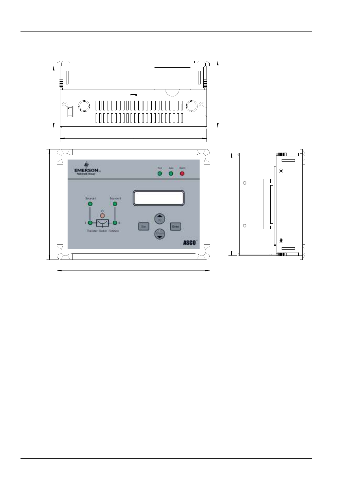
1.5 C2000 Controller Dimensions
189
197
80 86
1 2
142
Figure 1-2 Controller Dimensions (mm)

Chapter 2 Installation and Wiring 5
ASCO Series 2 0 Automatic Transfer Switch C2000 Intelligent Controller User Manual
Chapter 2 Installation and Wiring
DANGER
!
!!
!
DANGER is used in this manual to warn of a hazard situation which, if not avoided, will result in death or serious injury.
WARNING
!
!!
!
WARNING is used in this manual to warn of a hazardous situation which, if not avoided, could result death or serious
injury.
CAUTI N
!
!!
!
CAUTION is used in this manual to warn of a hazardous situation which, if not avoided, could result in minor or
moderate injury.
N TICE
NOTICE is used in this manual to comments or suggestion of a fault situation which, if not avoided, could result in
fault.
An experienced licensed electrician must install the ATS.
Each automatic transfer switch contains a rating label (Name plate) to define the loads (Ampere rating). Refer to the
label on the transfer switch for specific values.
DANGER
!
!!
!
Do not exceed the values on the rating label.
Exceeding the rating can cause personal injury or serious equipment damage.

6 Chapter 2 Installation and Wiring
Series 2 0 Automatic Transfer Switch C2000 Intelligent Controller User Manual
This chapter introduces the installation and wiring of the Controller.
WARNING
!
!!
!
1. The controller should be installed with the operation panel on the outside of the panel or door.
2. When doing any maintenance, Controller MUST BE disconnected from all power sources.
. Make sure the Controller is properly grounded with the Grounding Cable included with the Controller.
4. In order to avoid static buildup that can damage the controller electronics, the operators should wear an antistatic device.
WARNING
!
!!
!
This is a class A product, In a domestic environment this product may cause radio interference in which case the user may be
required to take adequate measures.
2.1 Installation
For installation into a door panel, the following opening dimensions are required in order to insert the Controller into the
panel.
191
±1
134
±1
Figure 2-1 Minimum Panel Opening Dimensions (mm)
Other manuals for 230 Series
1
Table of contents
Other Asco Switch manuals

Asco
Asco 7000 Series User manual

Asco
Asco 7000 Series User manual

Asco
Asco 7000 Series User manual

Asco
Asco Series 300 Installation guide

Asco
Asco Series 300 User manual

Asco
Asco Joucomatic 349 Series User manual

Asco
Asco 200 Series User manual

Asco
Asco 4000 series User manual

Asco
Asco 940 User manual

Asco
Asco 386 Series User manual

Asco
Asco Series 300 User manual

Asco
Asco 917 User manual

Asco
Asco 8344 Installation and operating instructions

Asco
Asco 3ATS User manual

Asco
Asco Series 300 User manual

Asco
Asco 230 Series User manual

Asco
Asco 940 User manual

Asco
Asco 920 User manual

Asco
Asco 7000 Series User manual

Asco
Asco J 4000 Series User manual


