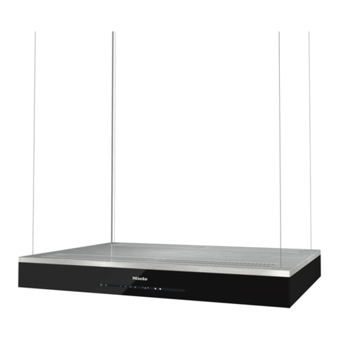
Arda range hood User manual
Page 16 - Warranty & Registraon
Page 2 - Safety Informaon
Owner’s Manual
Range Hoods
Page 4 - Wall Mount Hoods
Page 8 - Island Mount Hoods
Page 12 - Use & Care instrucons
Pour version française, visitez notre site à l’adresse www.ardaappliances.com
We do the utmost to ensure that the provided informaon is complete and accurate; however, images and
specicaons are subject to change without noce. Visit our website at www.ardaappliances.com
for the latest version of this manual.
- 2 -
TO REDUCE THE RISK OF FIRE, ELECTRICAL SHOCK OR PERSONAL INJURY,
PLEASE OBSERVE THE FOLLOWING:
1. Installaon and electrical work must be done by a qualied TECHNICIAN in
accordance with all applicable codes and standards.
2. If the supply cord is damaged, it must be replaced by the manufacturer,
its service agent or a similarly qualied person to avoid a hazard. Any
modicaons that may be required to the home’s electrical system for the
installaon of the range hood must only be made by qualied electricians.
3. Before servicing or cleaning unit, switch power o at the service panel.
Lock panel to prevent power from being switched on accidentally.
4. Use this unit only in the manner intended by the manufacturer.
5. Sucient air is needed for combuson and exhausng of gases through the
chimney of fuel burning equipment to prevent back draing. Follow the
heang equipment manufacturer’s guidelines and safety standards such as
those published by the Naonal Fire Protecon Associaon (NFPA), and the
American Society for Heang, Refrigeraon and Air Condioning Engineers
(ASHRAE), and the local code authories.
6. When cung or drilling into wall or ceiling, be careful NOT to Damage
exisng electrical wiring and other hidden ulies.
7. Ducted fans must always be vented to the outdoors.
8. To reduce the risk of re, use only metal ductwork.
9. This unit must be grounded.
!
We do the utmost to ensure that the provided informaon is complete and accurate; however, images and
specicaons are subject to change without noce. Visit our website at www.ardaappliances.com
for the latest version of this manual.
- 3 -
TO REDUCE THE RISK OF INJURY TO PERSONS IN THE EVENT OF A RANGE
TOP GREASE FIRE, OBSERVE THE FOLLOWING:
1. SMOTHER FLAMES with a close-ng lid, cookie sheet or metal tray, and
then turn o the burner. If the ames do not go out immediately, evacuate
and call the re department.
2. NEVER PICK UP A FLAMING PAN. – You may be burned.
3. DO NOT USE WATER, including wet dishcloths or towels – a violent steam
explosion may result.
4. Use an exnguisher ONLY if:
• You know you have a Class ABC exnguisher and you already know how
to operate it.
• The re is small and contained in the area where it started.
• The re department is being called.
• You can ght the re with your back to an exit.
1. To reduce the risk of re and to properly exhaust air, be sure to duct air
outside. Do not vent exhaust air into spaces within walls, ceilings or into
acs, crawl spaces or garages.
2. Take care when using cleaning agents or detergents.
3. Avoid using food products that produce ames BENEATH the range hood.
4. The range hood must only be used for the exhausng of cooking fumes in
DOMESTIC kitchens. The manufacturer disclaims all liability for any other
use of the appliance.
5. Two installers are recommended because of the large size and/or weight of
this hood.
6. Only use with 110/120V power plug provided.
7. Please read specicaon label on product for further informaon and
requirements.
!
We do the utmost to ensure that the provided informaon is complete and accurate; however, images and
specicaons are subject to change without noce. Visit our website at www.ardaappliances.com
for the latest version of this manual.
- 4 -
1. Read this manual carefully and completely.
2. ARDA range hoods conform to ETL/CSA standards. Check your local
building codes for any addional requirements.
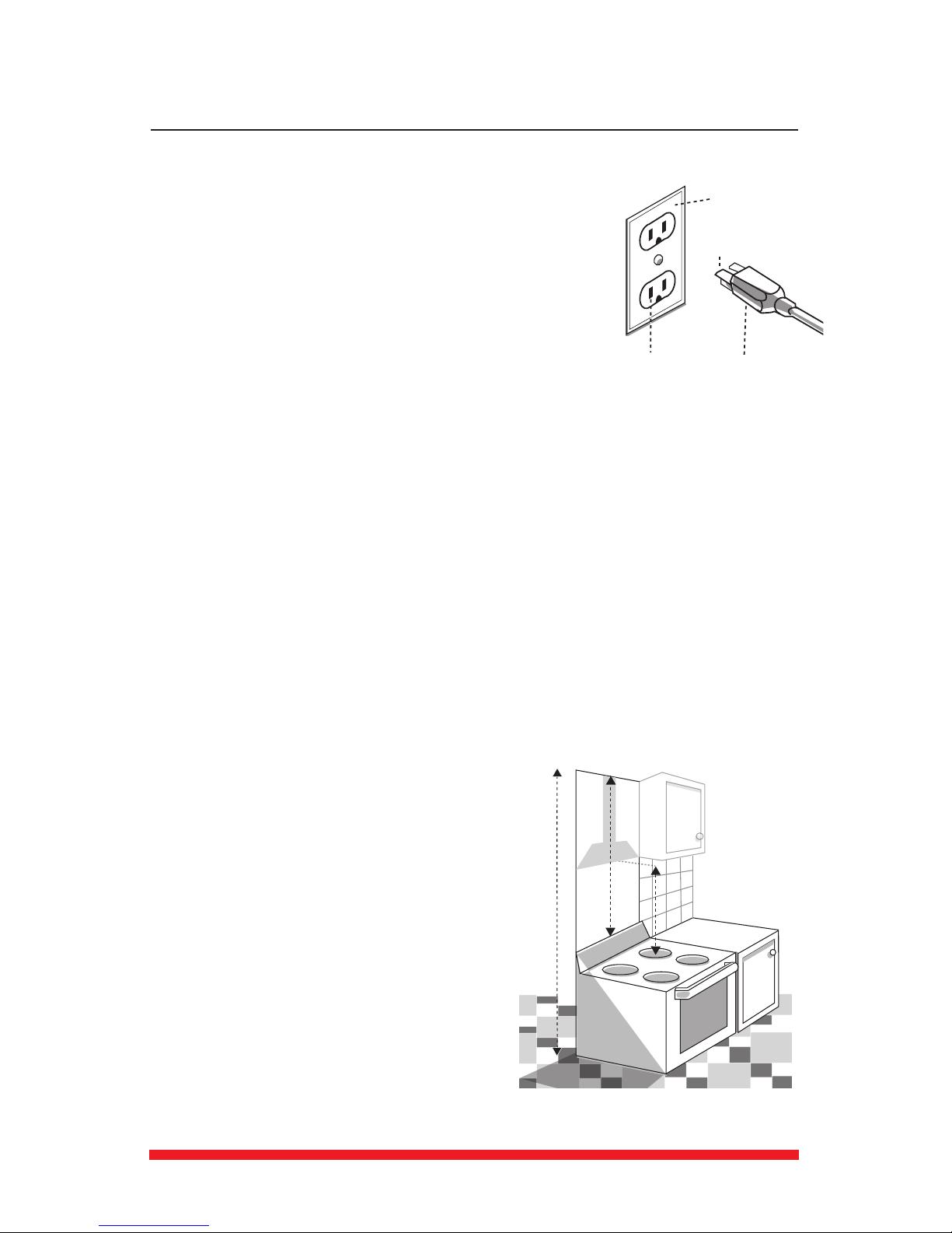
3. The appliance has been manufactured as Class I, therefore a
ground connecon is necessary. A 110/120V power cord with plug is
provided. The range hood must be installed so that the plug is easily
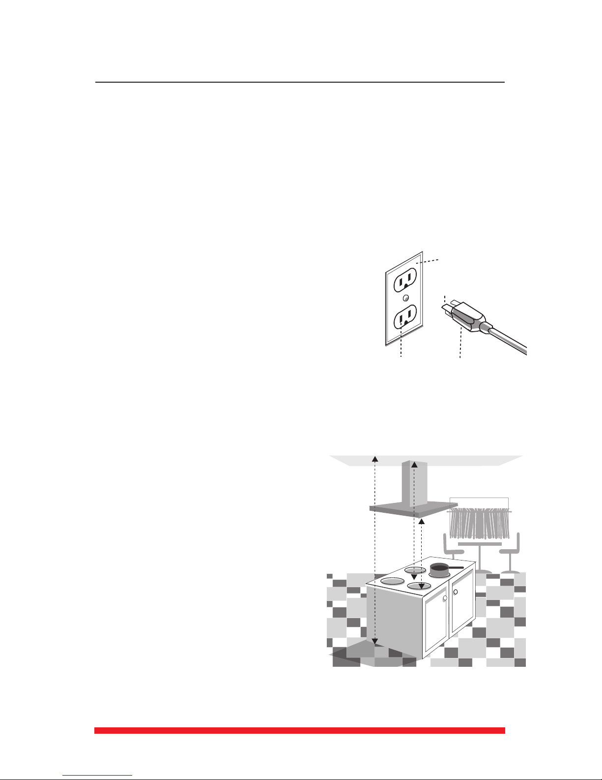
accessible (Fig. 1).
4. If appliance has been designed for use in both ducted and
recirculang modes, follow the appropriate installaon method. (For
recirculaon mode a kit is required – not included. Contact
Integrated Appliances, Ltd. to determine if a kit is available for your
hood.)
1. Measure:
a. The oor to ceiling height (A - Fig. 2).
b. Find the centre point of your opening. Mark a plumb line (B) through this point from ceiling to
your range/cook-top.
c. Check your range/cook-top user manual for the specied minimum and maximum distance
above your cooking surface. Mark the minimum clearance (C) on the centre line.
2. Decide where the ductwork will run between the hood and the outside. Short, straight duct
runs will provide the most air ow.
3. Installing a cross brace within the wall at the mounng height is recommended (see Step D -
Mounng Height Calculaon & Cross-Bracing Installaon).
4. Decide where to install the 110/120V receptacle within the dimensions of the decorave
chimney.
5. Calculate the required height of the decorave chimney. ARDA range hoods will usually t on
walls between 7½’ and 8 ½’ depending on the mounng height of the range hood. For a shorter
installaon you may need to have the provided chimney cut. For a taller installaon you may need
to fabricate an extension piece.
A - Floor to Ceiling height
B - Ceiling to Cooking Surface (center/plumb line) height
C- Cooking surface to boom of hood height
Outlet Cover
Grounding Pin
Grounded Outlet Plug
Fig. 1
A
C
B
Fig. 2
We do the utmost to ensure that the provided informaon is complete and accurate; however, images and
specicaons are subject to change without noce. Visit our website at www.ardaappliances.com
for the latest version of this manual.
- 5 -
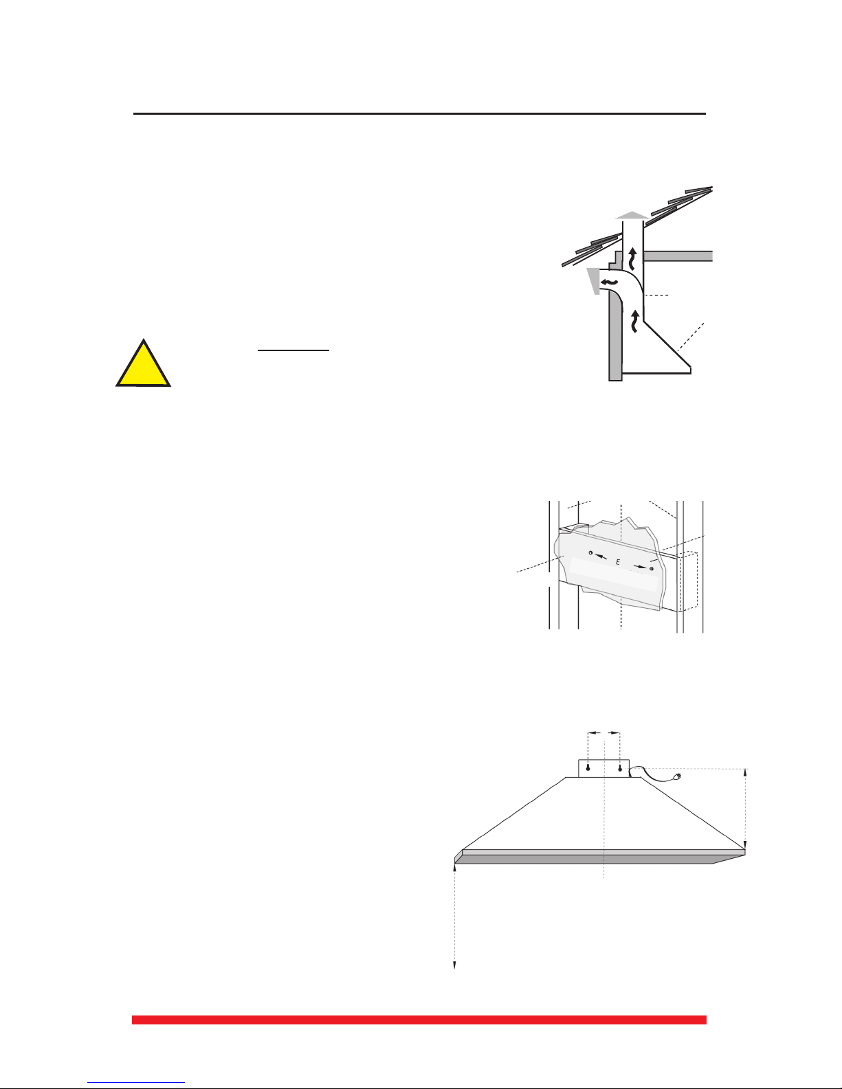
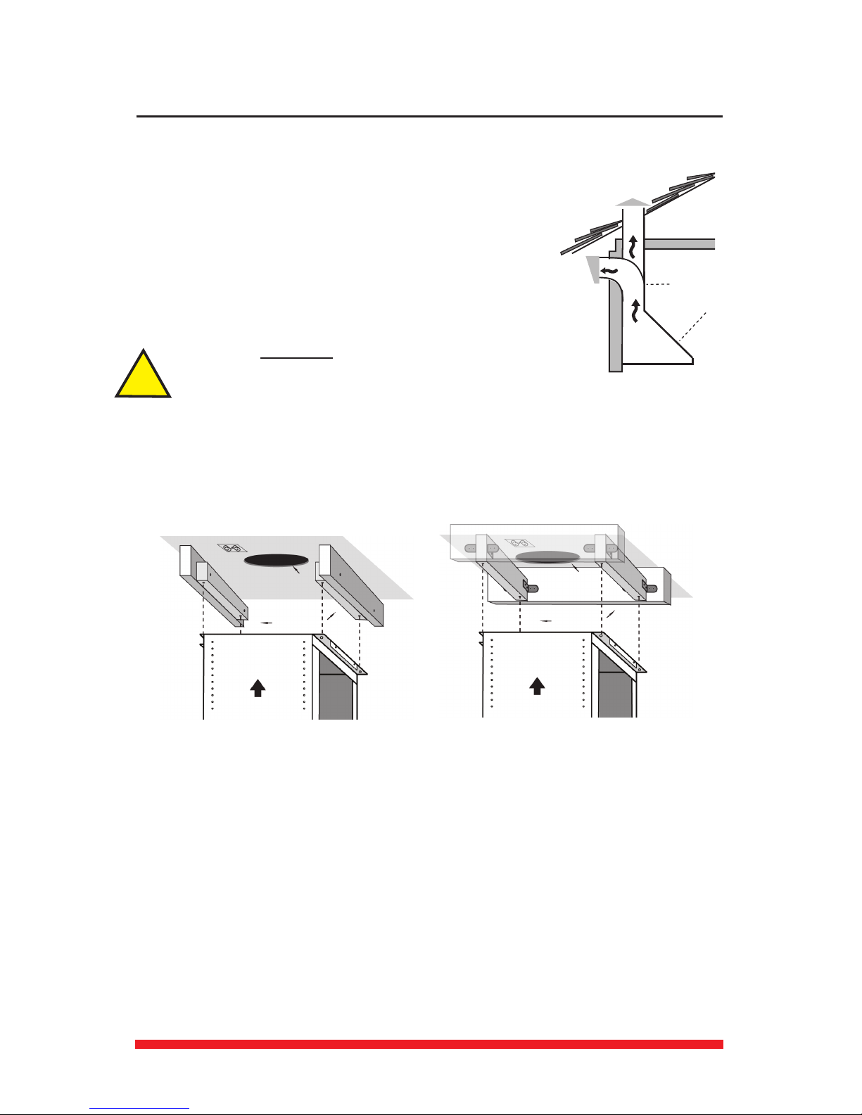
1. Arda hoods exhaust vercally up through the ceiling to the roof
(Fig. 3). They can be ducted to the rear behind the decorave
chimney duct through an outside wall.
2. Plan where the ductwork will run between the hood and the
outside.
3. A short straight duct run will produce the most air ow. Longer
lengths and elbow ducts will reduce the eciency of the blower.
4. Install a roof or wall cap outside your home. Connect a 6” round
metal duct to the cap and work backwards towards the hood. Ensure
connecons are completely sealed with duct tape.
5.
1. Decide on the mounng height of the hood (C - Fig. 2). You will need to consider the following:
In general the minimum mounng height above an electric
range is 24” and above a gas range is 30”. Check your range’s
installaon manual for the correct minimum mounng height
for your installaon.
Mounng the hood at a height where the
controls are at eye level is usually most convenient.
actors such as symmetry and alignment within your
backsplash and/or cabinetry.
of the decorave chimney.
2. Mark the mounng height (C) on the plumb line (B).
3. The mounng holes on the hood are used for aaching the
hood to the wall. Measure the distance between the boom of the hood and the top of the
mounng holes on the hood (D - Fig. 5). Draw a line perpendicular to the center/plumb line (B)
at this height. Measure the distance between the
mounng holes on the hood (E). Center and mark this
measurement on line D. Ensure that this measurement
is centered on either side of the center (plumb) line.
This is where the mounng holes are to be posioned.
4. Behind the drywall and any backsplash material, in-
stall cross-bracing between the wall joists at the level
of the mounng screw holes (Fig. 4)
5. Insert the mounng screws through the marked
mounng holes, leaving about 1/4” of the thread
exposed. Ensure you use the appropriate type of
screws for your wall/crossbracing.
!
Hood
Roof Cap
Wall Cap
Duct
Fig. 3
Fig. 4
Center line
Mounng Holes
Drywall
Framing
Wood
cross-
bracing
Fig. 5
Mounng Holes
E
Oset
Height
D
Center (Plumb)
Line
B
Mounng Height
(to cooktop)
C
We do the utmost to ensure that the provided informaon is complete and accurate; however, images and
specicaons are subject to change without noce. Visit our website at www.ardaappliances.com
for the latest version of this manual.
- 6 -
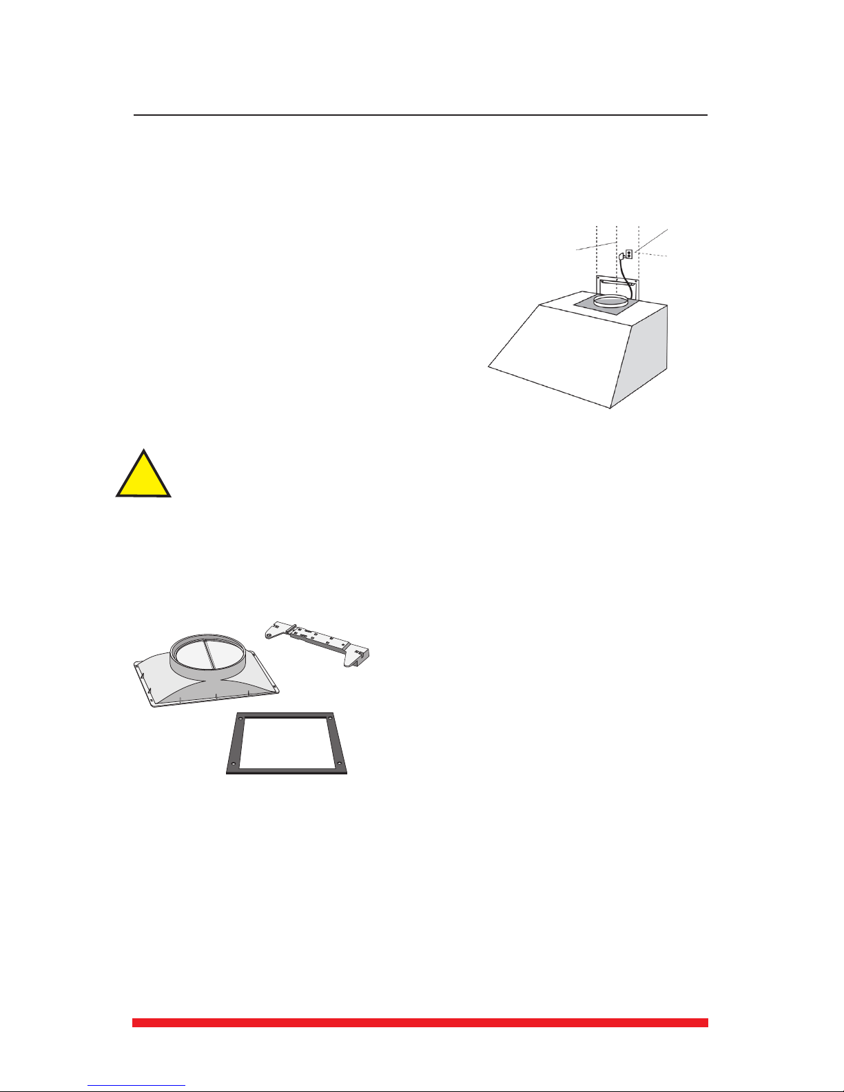
1. Install a 110/120V electric receptacle on the wall within the dimensions of the decorave
chimney (Fig. 6). Note that removal of the plug will void the
warranty of the range hood.
1. We recommend that two people mount the hood.
2.
3. Damper installaon :
Inside the hood, under the grease lters, you will nd the:
Damper (Fig. 7); Gasket (Fig. 8); Gasket screws (x 4); Wall bracket for the chimney (Fig. 9).
Set the bracket aside for use in Step G. Place the gasket on top of the hood. Place the damper
on top of the gasket. Using the screws provided, ax the damper to the hood.
When unpacking models HAM52A and HAM52B,
please note that the gasket and associated hardware
are packed inside the hood.
4. Before mounng the hood, plug the unit in and test all funcons for proper operaon:
5. Remove the grease lters from the boom of the hood to prevent damage during the
installaon.
6. With assistance from at least one other person, hold the hood temporarily in posion ensuring
the boom is above the minimum clearance for the cooking surface.
!
Fig.6
Center/plumb
Line B
Grounded
Outlet
Fig.7
Fig.8
Fig.9
We do the utmost to ensure that the provided informaon is complete and accurate; however, images and
specicaons are subject to change without noce. Visit our website at www.ardaappliances.com
for the latest version of this manual.
- 7 -
7. Mount the hood on the mounng screws. When the hood has been leveled, secure unit by
ghtening screws.
8. Connect a 6” aluminum duct tube (not included) between your hood and duct path. Ensure that
the damper aps are free to open. Seal all seams using duct tape.
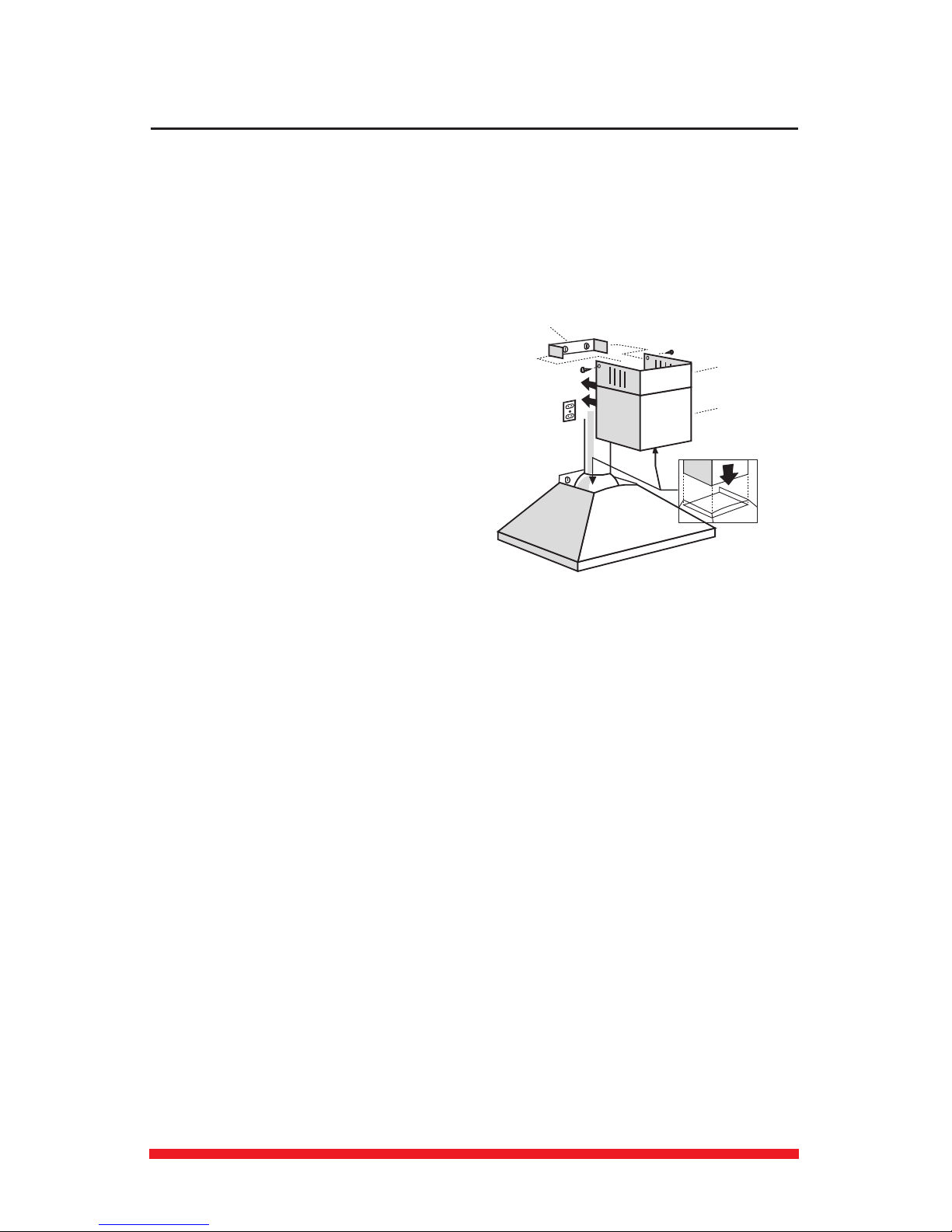
1. Carefully loosen but do not separate the
telescopic chimney duct pieces (A & B - Fig. 10). The
inside piece is the top and aaches to the wall at the
ceiling. The outside piece is the boom and rests on
the range hood.
2. Plug in the hood.
3. Install the recirculaon kit if required.
4. Aach the wall bracket.
: adjust the
width of the support bracket (D) to match the
upper duct width. Fix it to the wall using the
screws. Mark a line 4 mm down from the ceiling.
Fix the adaptor to the wall using the screws
provided so that it is centered in line with your hood and at a distance from the ceiling indicated.
: on the wall, at the ceiling edge, center the bracket on the plumb line.
Aach to the wall using screws appropriate to the wall material.
5. Place the two nested chimney pieces on top of the range hood. Draw the inside/top piece up to
the ceiling and ax to the wall bracket using the provided screws.
6. Remove the decorave plasc wrap from the hood.
A
B
D
C
C
A. Upper vent cover
B. Lower vent cover
C. Screws
D. Bracket
Arda
Fig.10
A. Upper vent cover
B. Lower vent cover
C. Screws
D. Bracket
We do the utmost to ensure that the provided informaon is complete and accurate; however, images and
specicaons are subject to change without noce. Visit our website at www.ardaappliances.com
for the latest version of this manual.
- 8 -
1. Read this manual carefully and completely.
2. ARDA range hoods conform to ETL/CSA standards. Please check your local building codes for any
addional requirements.
3. The appliance has been manufactured as Class I, therefore ground connecon is necessary.
A 110/120V plug is provided. The range hood must be installed so that that the plug is easily
accessible (Fig. 11).
4.If appliance has been designed for use in both ducted and recirculang modes, follow the
appropriate installaon method. (For recirculaon mode a kit is required – not included. Contact
Integrated Appliances to determine if a kit is available for your hood.)
1. Measure:
a. The oor to ceiling height (A - Fig. 12).
b. The distance from your cooking surface to your ceiling. (B)
c. Check your range/cooktop user manual for the specied min/
max hood distance (C) above your cooking surface.
2. Decide where the ductwork will run between the hood and the
outside. Short straight duct runs will provide the most air ow.
3. Find the centre point of your range/cooktop. Drop a plumb line
from your ceiling to this point on your cooking surface.
Mark the ceiling where the plumb line starts.
4. Calculate the required height of the mounng cage and
decorave chimney. ARDA range hoods will usually t on walls between 8 ½’ and 9 ½’ depending
on the mounng height of the range hood. For a shorter installaon you may need to have the
provided chimney and/or mounng cage cut. For a taller installaon you may need to fabricate an
extension piece.
A - Floor to Ceiling height
B - Ceiling to Cooking Surface (center/plumb line height
C - Cooking surface to boom of hood height
Outlet Cover
Grounding Pin
Grounded Outlet Plug
Fig.11
C
B
A
Fig.12
We do the utmost to ensure that the provided informaon is complete and accurate; however, images and
specicaons are subject to change without noce. Visit our website at www.ardaappliances.com
for the latest version of this manual.
- 9 -
1. Arda hoods exhaust vercally up through the ceiling to the roof
(Fig. 13). They can be ducted to the rear behind the decorave
chimney duct through an outside wall.
2. Plan where the ductwork will run between the hood and the
outside.
3. A short straight duct run will produce the most air ow. Longer
lengths and elbow ducts will reduce the eciency of the blower.
4. Install a roof or wall cap outside your home. Connect a 6” round
metal duct to the cap and work backwards towards the hood.
Ensure connecons are completely sealed with duct tape.
5.
1. In the ceiling, install cross-braces between the ceiling joists (Figs. 14a and 14b).
the boom of the cross-bracing must be level to ensure that the island hood hangs
level.
1. Install a 110/120V receptacle on the ceiling within the dimensions of the decorave chimney
(Fig. 14a). that the removal of the plug will void the warranty of the range hood.
Fig. 14b
Fig. 14a
!
Hood
Roof Cap
Wall Cap
Duct
Fig. 13
We do the utmost to ensure that the provided informaon is complete and accurate; however, images and
specicaons are subject to change without noce. Visit our website at www.ardaappliances.com
for the latest version of this manual.
- 10 -
1. For an island hood installaon, you will need
to consider the following when calculang the
mounng height (C - Fig. 12 on p.8):
In general the
minimum mounng height above an electric
range is 24” and above a gas range is 30”.
Check your range’s installaon manual for the
correct minimum mounng height for your
installaon.
On an island hood, mounng
the hood at a height where the controls are at
eye level is usually most convenient.
Factors such as symmetry and alignment within your backsplash or cabinetry.
of the decorave chimney.
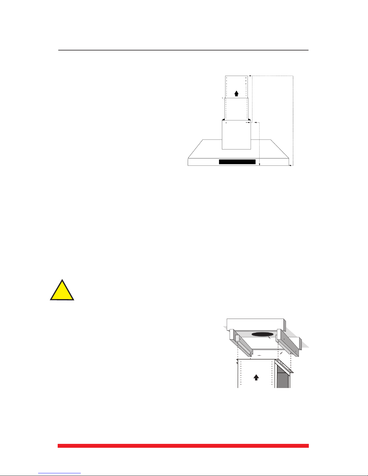
2. Calculate the available height from the ceiling to the boom of the hood (X - Fig. 15). Calculate
the height of the hood (Y), then calculate the extended height for the mounng cage (Z).
3. Expand the telescopic cage to the calculated size (Z). Use the screws provided to x the
telescopic cage in place. If the calculated height of the mounng cage is smaller than the actual
height of the cage, you will need to have both the cage and the decorave chimneys cut to t
your installaon. We recommend that a stainless steel fabricator do this to ensure a straight even
cut. If the calculated height of the mounng cage is larger than the actual height of the cage,
you will need to fabricate an extension piece. Please call our oce at 1-800-268-4086 or info@
ardaappliances.com for assistance if required.
1. Centre the upper cage on the ceiling around the exhaust duct
opening. Ensure that:
a. The markings coincide with the cross-bracings between the
ceiling joints.
b. The cage is square with the cooking surface below.
c. The side of the cage that has the arrow on it faces the front.
When installed, this is the side of the hood that will have the
controls.
2. Mark the upper screw holes on the ceiling (Fig. 16).
3. Parally screw the four mounng screws provided into the
ceiling at these markings.
4. Ensure that the unit is square and level then completely ghten the screws. The cage should
now be rmly aached to the ceiling.
5. If you have not done so previously, insert the lower cage over the upper cage. Adjust the height
to the necessary distance using screws supplied.
Fig.15
X
Y
Z
Telescopic
!
Fig.16
Table of contents
Other Arda Ventilation Hood manuals