Aquafog Turbo XE Manual

MODEL:
XE-2000-EXP
Read & Understand
Retain for Future Reference
TURBO XE ATOMIZER
USER'S MANUAL AND OPERATING INSTRUCTIONS
OPERATOR'S MANUAL
NOTICE
UL and CSA Electrical Components
Rear-Feed
XE

General Safety . . . . . . . . . . . . . . . . . . . . . . . .
Preparation . . . . . . . . . . . . . . . . . . . . . . . . . . .
Placement . . . . . . . . . . . . . . . . . . . . . . . .
Installation . . . . . . . . . . . . . . . . . . . . . . . . . . .
- motor & tubing . . . . . . . . . . . . . . . . . . . .
- installing blade assembly . . . . . . . . . . .
- housing & pivot adjustment . . . . . . .
- connecting water & power . . . . . .
Operation . . . . . . . . . . . . . . . . . . . . . . . . . .
Common Setups . . . . . . . . . . . . . . . . . . . .
Troubleshooting . . . . . . . . . . . . . . . . .
Turbo XE Exploded View . . . . . . . . . . . .
Flowmeter Exploded View . . . . . . . . . . . . . .
Part Identication List . . . . . . . . . . . . . . . .
Maintenance . . . . . . . . . . . . . . . . . . . . . . . .
Warranty . . . . . . . . . . . . . . . . . . . . . . . . . . .
2
PAGE
3
4
5 - 6
7
8
9
10
11 - 12
13
14
15 - 16
17 - 18
19
20
21
22
Description
Aquafog units are intended to condition large
volumes of air using water or other non-hazardous
liquids at air temperatures between 31ºF and 145ºF.
Any other use of these units will void the warranty
and the manufacturer will not be responsible for
problems or damages resulting from misuse.
Safety Guidelines
This manual contains very important information.
This information will help ensure SAFETY and
PREVENT EQUIPMENT PROBLEMS. Use these
symbols to understand safety guidelines.
DANGER DANGER INDICATES AN
IMMINENTLY HAZARDOUS
SITUATION WHICH, IF NOT AVOIDED, WILL RESULT IN
DEATH OR SERIOUS INJURY.
WARNING INDICATES A
POTENTIALLY HAZARDOUS
SITUATION WHICH, IF NOT AVOIDED, COULD RESULT IN
DEATH OR SERIOUS INJURY.
CAUTION INDICATES A
POTENTIALLY HAZARDOUS
SITUATION WHICH, IF NOT AVOIDED, MAY RESULT IN
MINOR OR MODERATE INJURY.
NOTICE INDICATES IMPORTANT
INFORMATION, THAT IF NOT
FOLLOWED, MAY CAUSE DAMAGE TO EQUIPMENT.
table of contents
WARNING
CAUTION
NOTICE
Notes

DANGER
3
12. When Turbo XE-EXP are
automated by controls, warning
signs should be posted near
the high-speed equipment.
13. Disconnect and lock-out power
source to inspect or service the unit.
ABB Explosion-Proof motors are UL and
CSA approved for the following hazardous
locations:
CLASS 1, Group D locations
containing volatile gases
such as Gasoline, Hexane,
Naphtha, Benzine,
Propane, Alcohol etc.
CLASS 2, Group F & G
locations containing dust
such as (F) Carbon Black, Coal or Coke Dust
or (G) Flour, Starch, or Grain Dusts.
General safety
Since the Turbo XE-EXP uses high-speed components
to atomize liquids, the following safety precautions
must be observed at all times:
1. Read all manuals included
with this product. Be familiar
with the product and controls.
2. Follow United States
Environmental Protection Agency (EPA)
guidelines and regulations when fogging
pesticide or chemical solutions.
3. Always operate Turbo XE-EXP with it's safety
guards and housing securely attached.
4. Follow all local electrical and safety codes
as well as the United States National
Electrical Codes (NEC) and Occupational Safety
and Health Act (OSHA).
5. Only persons well acquainted with these rules
of safe operation should be allowed to use the
atomizer.
6. Keep visitors away and NEVER allow children in
the work area.
7. Use of an extension cord for the Turbo XE is
not recommended. If necessary, consult a
certied electrician about use of a heavy-
gauge, grounded extension cord.
8. Before each use, inspect blade assembly
and electrical components for signs of damage,
deterioration, weakness or leakage. Repair or
replace defective items before using.
9. Check all fasteners at frequent intervals for
proper tightness.
10. Keep ngers away from a running unit; fast
moving and hot parts will cause injury and/or
burns.
11. If the equipment starts to vibrate abnormally,
STOP the motor and check immediately for
the cause. Vibration is generally an indication
of trouble.
DO NOT ATOMIZE
FLAMMABLE MATERIALS.
1. Humidity and cold air are
two common asthma triggers.
Asthmatic people working
with this equipment need to
be made aware of the risk.
2. When atomizing toxic chemicals, follow the
instructions provided by the chemical
manufacturer.
HIGH-SPEED ROTATION. A
MOTIONLESS ATOMIZER MAY
APPEAR SAFE, BUT ITS BLADE COULD SUDDENLY BEGIN
HIGH-SPEED ROTATION WITHOUT WARNING AS A RESULT
OF CONTROL PROGRAMMING.
DANGER
HAZARDOUS DUTY
CERTIFICATION
Fogging Precautions
NOTICE
NEVER OPERATE UNIT WITHOUT
THE HOUSING INSTALLED.
WARNING

4
preparation
Hardware CHeCklist tools required
unpaCking pre-installation
Detach housing assembly by using the 5/32" allen
wrench to remove the six cap screws securing the
housing assembly to the framework assembly.
(See Fig. 1)
Store hardware in safe location for later use.
After unpacking the unit, inspect for any damage
that may have occurred during transit. Make sure to
tighten ttings, bolts, etc., before operation.
DO NOT OPERATE UNIT IF
DAMAGED DURING SHIPPING,
HANDLING OR USE. DAMAGE MAY RESULT IN BREAKAGE
AND CAUSE INJURY OR PROPERTY DAMAGE.
WARNING
AQUA
FOG
(2) 1/4-20" SST U-bolt
(4) 1/4" at washer, lock washer, nut
(4) 1/4-20 nylon stop nut SST
(4) 5/16-18 bolt, at washer, lockwasher, nut
(6) wire tie
►Level
►7/16" wrenches
►1/2" wrenches
►3/32" allen wrench
►5/32" allen wrench
Fig. 1
Housing
Assembly
Framework
Assembly
1/4-20 x 3/8" button
head cap screw (54)
REMOVING
Housing Assembly
◄
USA

5
placement
Mount the fan high overhead. Allow room in front of and below the fan for the
unobstructed propulsion of fog. Rule of thumb: the higher the better, but mount at least three
feet away from any roong structures.
Mount the fan at the intake end of a ventilated structure. In structures with mild to no
ventilation, propel fog the length of the structure. In large structures, use of an oscillator greatly
enhances coverage and circulation.
DO NOT: Mount the fan near the ground or underneath tables or benches.
DO NOT: Propel the fog into the wind (direction of airow).
DO NOT: Cramp the fan in tight quarters or skinny aisle ways.
>
>
>>
>
25'
50'
70'
Intake
End
Intake
End
Control areaIn applications requiring only one unit, mount
the fan high, centered along one wall, with fog
propelling horizontally along the length of the
structure. If there is ventilation, mount the fan
at the intake end of the structure. Generally, no
oscillation is necessary unless the width of the
structure is greater than 20'. The best location
for automated controls is behind the fan, at an
easily accessible level for monitoring.
In large structures equipped with forced
ventilation, the rst fan row should be within a
few feet of the intake end, with rst fan:
- centered along the end wall (or)
- placed no more than 25' from the side wall,
with additional fans in the row equally spaced
no more than 50' apart.
Lengthwise, the fans should be equally spaced
no farther than 70' apart. All fans should be
equipped with oscillation, sweeping 180˚ in the
direction of the airow.
Layout Guidelines
AVERAGE DISTANCE COVERAGE CAPABILITY - 50 to 85 feet
Large structures, Force ventilation
Small structures
LOCATE A LEVEL AREA TO SET UP A STAND. TO HANG THE
UNIT, SECURE AND LEVEL 1" PIPE ABLE TO SUPPORT 80 LBS.
NOTICE
Placement Guidelines
>
Direction of airow

6
placement (cont.)
>
>
>
60'
>
>
60'
>
30'
>
>
30'
Large structures, Natural ventilation
In large structures with natural ventilation, propel fog
the length of the structure with the rst fan row no
more than 30' from the end wall. The rst fan should
be:
- centered along the end wall (or)
- placed no more than 30' from the side wall, with
additional fans in the row equally spaced no
farther than 60' apart.
Lengthwise, the fans should be equally spaced and no
more than 60' apart. All fans should be equipped with
oscillation, sweeping 360˚.
Large structures,
Closed or minimum ventilation
In closed structures with little to no ventilation, propel
fog the length of the structure with the rst fan row no
more than 50' from the end wall. The rst fan should
either be:
- centered along the end wall (or)
- placed no more than 50' from the side wall, with
additional fans in the row equally spaced
no farther than 100' apart.
Lengthwise, the fans should be equally spaced and no
farther than 100' apart. All fans should be equipped
with oscillation, sweeping 360˚.
>
>
>
100'
>
>
100'
>
50'
>
>
50'
USA
7
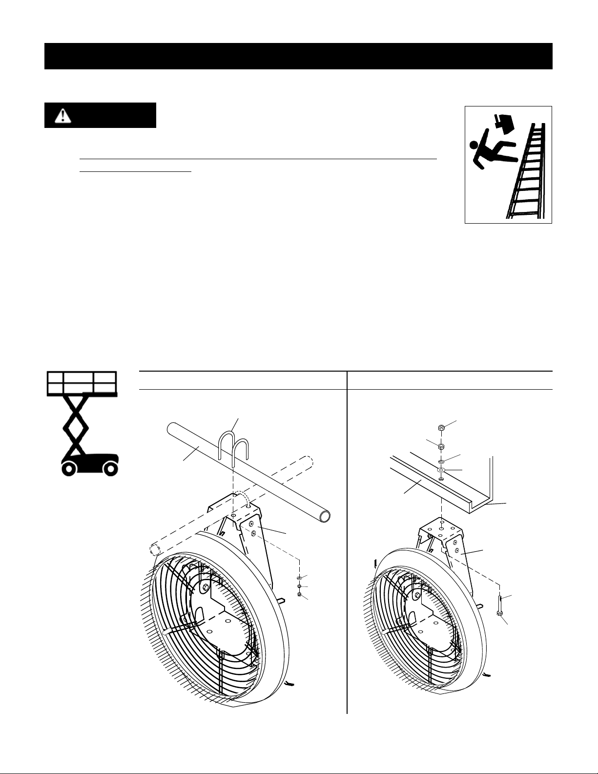
Attach Framework Assembly
Securing To Pipe - Use U-bolts provided. Tighten securely. The second nylon
lock-nut (Part #32) should be tightened on top of the rst nut to provide added
protection.
Universal Mount - The support should be secure, level and at. Drill a 5/16"
clearance hole. It is VERY IMPORTANT to tighten the second nylon lock-nut (Part
#395) on top of the rst nut (Part #116). Jam the two together for a secure
mount.
Note: Anti-seize applied to the bolt is to prevent the stainless steel from galling.
installation
USING A LADDER TO HANG THE TURBO XE IS DANGEROUS.
USE PROPER LIFTING EQUIPMENT LIKE A SCISSOR LIFT.
DANGER
(A) Secure to Pipe
Framework
Assembly
Support Bar
(not provided)
Fig. 2
1/4-20 U-bolt SST (#125)
#126
#154
#32
(A) Universal Mount
USA
Framework
Assembly
5/16" Clearance
Hole In Support
#518
#58
#395
#116
#57
Anti-
seize
Required Use
(see above)
Flat &
Level
NOTE: THIS UNIT IS SPECIFICALLY DESIGNED ONLY TO BE HUNG WITH IT'S MOTOR IN
THE UPRIGHT POSITION.

USA
8
Fig. 3
Install Motor
Slide the motor onto the motor support
plate of the framework assembly (as
shown in Fig. 3). Secure the base of the
motor to the motor support plate using
5/16" hardware provided (Part #56, 57,
58, 116) four each.
Tighten hardware by hand at this stage,
as nal tightening will follow the blade
adjustment procedure.
installinG motor & Water tubinG
#57
#116
#58
10-2002
#56
Fig. 4
Rear
Tube Ring
Front
Retaining Hole
1/4" OD
Tubing
Feed Tube
Assembly Front
Retaining Hole
1.5" Max
from face
of motor
1/4"
Tubing
Install Tubing
Route the 1/4" OD tubing provided through the rear tubing ring and through the front retaining hole
and into the 1/4" tube tting at the Feed Tube Assembly (see Fig. 4).
Tighten only about 1/2 turn past nger tight. Using 7/16" wrench.
Optional 3/8" tubing, at the front, use a square in the rear guard directly below centre frame bolt.
IMPORTANT: Keep tubing routed close to the motor, within 1.5" to maintain proper clearance from the
fan blade.
USA
XE

USA
9
Fig. 6
Check Blade Clearance & Secure Motor
Once the blade assembly is secured to the motor, rotate it by
hand to check for a centered circular rotation and clearance
greather than 1/8”
If a horizontal adjustment is needed, loosen the four
(4) motor bolts (Part #56) securing the motor to the frame
assembly and shift motor from side to side until centered.
Tighten bolts securely.
ENSURE THE BLADE ASSEMBLY IS CENTERED
INSIDE THE PINNED VENTURI. ADJUST MOTOR
IF NECESSARY.
CAUTION
Install Blade Assembly
Line up the key way and slide the Blade Assembly onto the motor shaft until ush to the end of shaft.
NOTE: Make sure the Feed Tube has clearance and does not touch while it enters the reserivor in back
of the Blade Assembly.
Using 3/32" allen wrench (provided) secure two (2) set screws. (see Fig. 5)
USA
installinG blaDe assembly
Blade Assembly
Feed Tube
Fig. 5
Set Screw
Flush to
end of shaft
Blade Assembly

XE
USA
10
HousinG re-attacHment & pivot
Pivot Locking System
After securing the hanging unit,apivot adjustment
can be made to direct the fogging output to a
desired location.
This unit has a positive pivot locking system with
four available positions.
~5º up
~Horizional
~7º down
~14º down
To Make an Adjustment
Balance the weight of the unit and lift one pivot
lock up and rest it in the middle of the "M". While
supporting the unit lift the second lock up.
Adjust unit to desired angle. Re-engage both locks
into the closest available slot.
NOTE: Use both legs of the "M" to get availability of
all four pivot angles.
Pivot
Joint
Pivot
Lock
Attaching Housing
Locate the six cap screws set aside
during preparation. (Refer to Fig. 1)
Reposition the housing over the
venturi starting with the lower
half of the housing. Tilt housing
downward to clear the lower lip of
the venturi. Raise the rear edge of
the housing between the venturi
and rear guard. (See Fig. 7)
Using the 5/32" allen wrench
(provided) secure housing to the
rear guard.
Fig. 7
1/4-20 x 3/8"
button head
cap screw (#54)
Housing
Assembly
Venturi
◄
AQUA
FOG
Other manuals for Turbo XE
1
This manual suits for next models
1
Table of contents
Other Aquafog Electronic Cigarette manuals

Aquafog
Aquafog XE HRSM Manual

Aquafog
Aquafog HRSM-2001 Manual

Aquafog
Aquafog HRSM-2000 Manual

Aquafog
Aquafog XE ORSM Manual

Aquafog
Aquafog XE CRSM User manual

Aquafog
Aquafog HYDRO SS 700 User manual

Aquafog
Aquafog XE 2000-HS Manual

Aquafog
Aquafog GT 500-HS Manual

Aquafog
Aquafog Turbo XE Manual

Aquafog
Aquafog XE-HRSM-2000-EXP Manual


