Anvil MWA1400 User manual

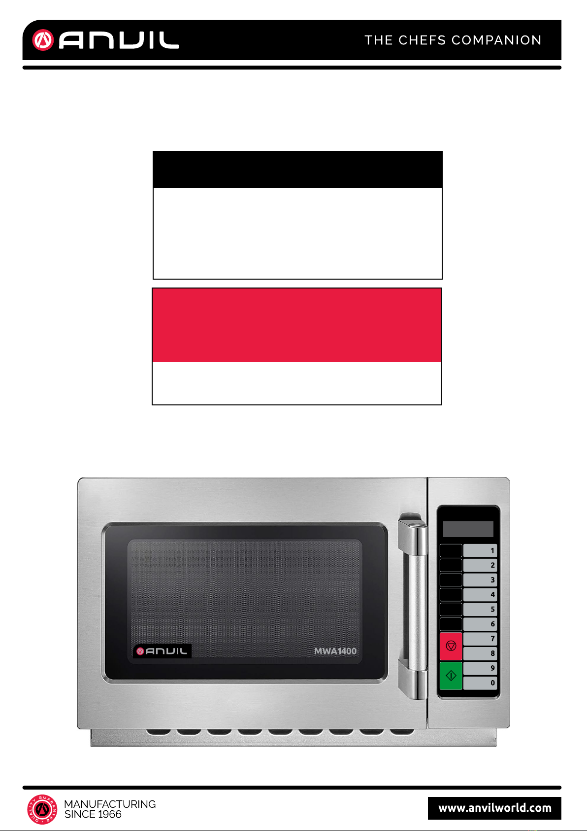
MWA1400
Service Manual
Commercial Microwave Oven
Caution:
Our ongoing committment to improving performance
and reliability means that parts listed in this manual
may be changed without prior notice.
For service and spare parts enquiries please contact
International Catering Equipment on (02) 8372 0800.
Anvil imported and distributed by
International Catering Equipment
Unit B2, 6-10 Durdans Avenue,
Rosebery NSW 2018 Australia
Ph: +61 2 8372 0800
www.internationalcatering.com.au
20%
POWER
0%
POWER
70%
POWER
50%
POWER
TIME
DOUBLE
QUANTITY
STOP
CLEAR
STA RT
+10 SEC
1
1
PRECAUTIONS TO BE OBSERVED BEFORE AND
DURING SERVICING TO AVOID POSSIBLE
EXPOSURE TO EXCESSIVE MICROWAVE ENERGY
(a) Do not operate or allow the oven to be operated with the door open.
(b) Make the following safety checks on all ovens to be serviced before activating the magnetron or other micro-
wave source, and make repairs as necessary: (1) Interlock operation, (2) Proper door closing, (3) Seal and
sealing surfaces (arcing, wear, and other damage), (4) Damage to or loosening of hinges and latches, (5)
Evidence of dropping or abuse.
(c) Before turning on power to the microwave oven for any service test or inspection within the microwave gen-
erating compartments, check the magnetron, wave guide or transmission line, and cavity for proper align-
ment, integrity, and connections.
(d) Any defective or misadjusted components in the interlock, monitor, door seal, and microwave generation
and transmission systems shall be repaired, replaced, or adjusted by procedures described in this manual
before the oven is released to the owner.
(e) A microwave leakage check to verify compliance with the federal performance standard should be per-
formed on each oven prior to release to the owner.
TABLE OF CONTENTS
PRECAUTIONS TO BE OBSERVED BEFORE AND DURING SERVICING TO AVOID POSSIBLE
EXPOSURE TO EXCESSIVE MICROWAVE ENERGY ......................................................................................................1
SAFETY AND PRECAUTIONS ...........................................................................................................................................2
1. FOR SAFE OPERATION ..................................................................................................................................2
2. FOR SAFE SERVICE PROCEDURES .............................................................................................................2
SPECIFICATIONS ...............................................................................................................................................................3
EXTERNAL VIEW................................................................................................................................................................4
1. OUTER DIMENSION.........................................................................................................................................4
2. FEATURES DIAGRAM......................................................................................................................................4
3. CONTROL PANEL ............................................................................................................................................5
INSTALLATION ...................................................................................................................................................................7
OPERATIONS AND FUNCTIONS.......................................................................................................................................8
DISASSEMBLY AND ASSEMBLY......................................................................................................................................9
INTERLOCK MECHANISM AND ADJUSTMENT.............................................................................................................16
TROUBLESHOOTING GUIDE ..........................................................................................................................................17
MEASUREMENT AND TEST ............................................................................................................................................21
1. MEASUREMENT OF THE MICROWAVE POWER OUTPUT ........................................................................21
2. MICROWAVE RADIATION TEST ...................................................................................................................22
3.
TEST PROCEDURE ........................................................................................................................................23
WIRING DIAGRAM............................................................................................................................................................24
PRINTED CIRCUIT BOARD..............................................................................................................................................25
1. CIRCUIT CHECK PROCEDURE ....................................................................................................................25
2. PCB CIRCUIT DIAGRAM................................................................................................................................30
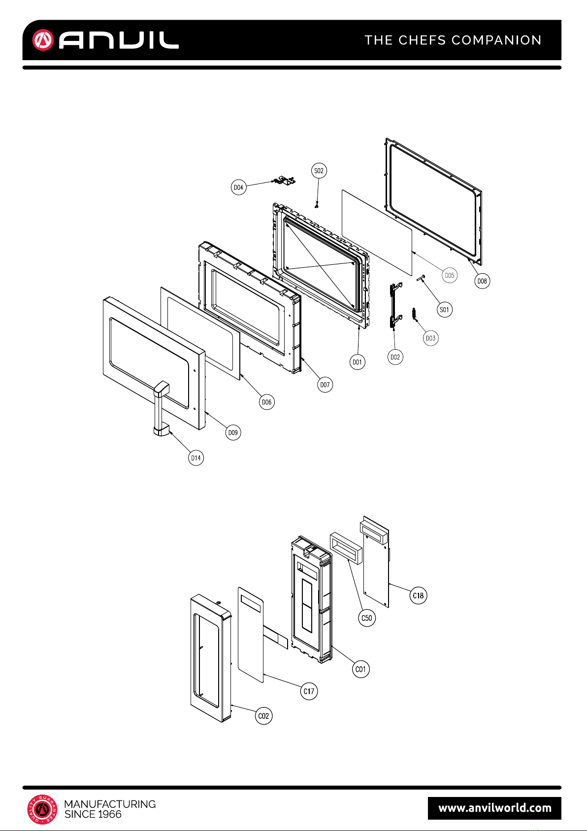
EXPLODED VIEW AND PARTS LIST...............................................................................................................................31
1.
DOOR ASSEMBLY .........................................................................................................................................31
2.
CONTROL PANEL ASSEMBLY......................................................................................................................31
3.
GUIDE WIND ASSEMBLY ..............................................................................................................................31
4.
TOTAL ASSEMBLY.........................................................................................................................................31
TABLE OF CONTENTS
CAUTIONS.....................................................................................................................................................................2
INSTALLATIONS ...........................................................................................................................................................3
SERVICE INFORMATION..............................................................................................................................................4
CIRCUIT DESCRIPTION.........................................................................................................................................4
PARTS LIST .........................................................................................................................................................5-6
PARTS DIAGRAM................................................................................................................................................7-8
TOOLS AND MEASURING INSTRUMENTS..........................................................................................................9
MICROWAVE LEAKAGE TEST..............................................................................................................................9
MEASUREMENT OF MICROWAVE POWER OUTPUT.......................................................................................10
DISASSEMBLY AND ADJUSTMENT ................................................................................................................... 11
1. Removing The Door..........................................................................................................................................12
2. Removing The Antenna Stirrer System ............................................................................................................12
3. Removing The Cooling Fan..............................................................................................................................13
4. High Voltage Transformer Removal..................................................................................................................13
5. High Voltage Capacitor And Diode Removal ....................................................................................................13
6. Magnetron Removal .........................................................................................................................................14
7. Removing The Turn Motor ................................................................................................................................14
8. Pcb Assembly Removal....................................................................................................................................14
9. Interlock System ...............................................................................................................................................14
INTERLOCK CONTINUITY TEST.........................................................................................................................15
1. Primary Interlock Switch Test............................................................................................................................15
2. Secondary Interlock Switch Test.......................................................................................................................15
3. Monitor Switch Test...........................................................................................................................................15
COMPONENT TEST PROCEDURE .....................................................................................................................16
TROUBLE SHOOTING .........................................................................................................................................20
2
• DO NOToperate on a 2-wire extension cord during
repair and use.
• NEVER TOUCHany oven components or wiring during
operation.
• BEFORE TOUCHING any parts of the oven, always
remove the power plug from the outlet.
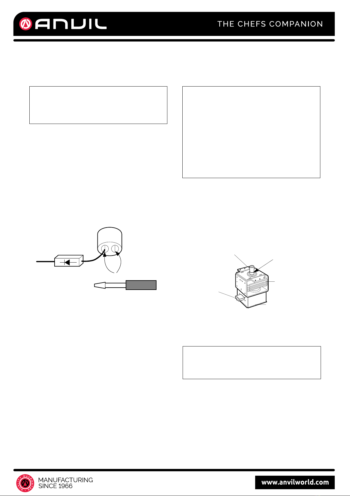
• For about 30 seconds after the oven stops, an electric
charge remains in the high voltage capacitor. When
replacing or checking, you must discharge the high
voltage capacitor by shorting across the two terminals
with an insulated screwdriver.
•
Remove your watches whenever working close to or
replacing the Magnetron.
• NEVERoperate the oven with no load.
•NEVERinjure the door seal and front plate of the oven
cavity.
• NEVERput iron tools on the magnetron.
• NEVERput anything into the latch hole and the
interlock switches area.
• Proper operation of the microwave oven requires that
the magnetron be assembled to the waveguide and
cavity. Never operate the magnetron unless it is
properly installed.
• Be sure that the magnetron gasket is properly
installed around the dome of the tube whenever
installing the magnetron.
CAUTIONS
Unlike other appliances, the microwave oven is
high-voltage and high-current equipment.
Though it is free from danger in ordinary use,
extreme care should be taken during repair.
THE OVEN IS TO BE SERVICED ONLY
BY PROPERLY QUALIFIED SERVICE
PERSONNEL.
MICROWAVE RADIATION
Personnel should not be exposed to the
microwave energy which may radiate from the
magnetron or other microwave generating
device if it is improperly used or connection.
All input and output microwave connections,
waveguide, flange and gasket must be secure
never operate the device without a microwave
energy absorbing load attached.
Never look into an open waveguide or antenna
while the device is energized.
ANTENNA
COOLING FIN
MAGNETRON
CHASSIS GROUND
FILAMENT
TERMINALS
MAGNETRON
GASKET
1
CAUTIONS
3
INSTALLATIONS
INSTALLING
1. Empty the microwave oven and clean inside it with
a soft, damp cloth. Check for damage such as
misaligned door, damage around the door or dents
inside the cavity or on the exterior.
2. Put the oven on a counter, table, or shelf that is
strong enough to hold the oven and the food and
utensils you put in it. (The control panel side of the
oven is the heavy side. Use care when handling.)
3. Do not block the vent and the air intake openings.
Blocking vent or air intake openings can cause
damage to the oven and poor cooking results.
Make sure the microwave oven legs are in place to
ensure proper air flow.
4. The oven should not be installed in any area where
heat and steam are generated, because they may
damage the electronic or mechanical parts of the
unit.
Do not install the oven next to a conventional
surface unit or above a conventional wall oven.
5. Use microwave oven in an ambient temperature
less than 104°F(40°C).
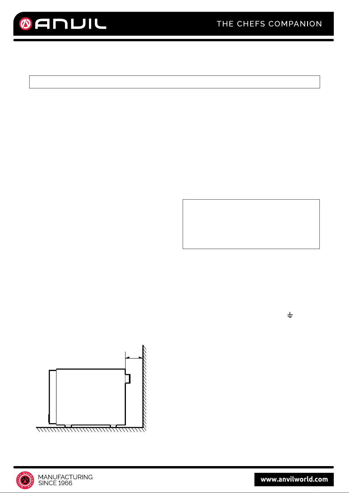
6. Place the microwave oven on a sturdy and flat
surface at least 10 cm(4 inches) from the wall.
7. Place the microwave oven as far away as possible
from TV, RADIO, COMPUTER, etc., to prevent
interference.
EARTHING INSTRUCTIONS
This microwave oven is designed to be used in a fully
earthed condition.
It is imperative, therefore, to make sure it is properly
earthed before servicing
WARNING-
THIS APPLIANCE
MUST BE EARTHED
IMPORTANT
As the colors of the wires in the mains lead of this
appliance may not correspond with the colored
markings identifying the terminals in your plug,
proceed as follows.
The wire which is colored green-and-yellow must be
connected to the terminal in the plug which is marked
with the letter E or by the earth symbol ( ) or
colored green or green-and-yellow .
The wire which is colored blue must be connected to
the terminal in the plug which is marked with the letter
N or colored black .
The wire which is colored brown must be connected
to the terminal in the plug which is marked with the
letter L or colored red.
BEFORE YOU BEGIN, READ THE FOLLOWING INSTRUCTIONS COMPLETELY AND CAREFULLY.
10cm
The wires in this mains lead are colored in
accordance with the following code:
Green-and-yellow: Earth
Blue: Neutral
Brown: Live
2
INSTALLATIONS
INSTALLING
1. Empty the microwave oven and clean inside it with
a soft, damp cloth. Check for damage such as
misaligned door, damage around the door or dents
inside the cavity or on the exterior.
2. Put the oven on a counter, table, or shelf that is
strong enough to hold the oven and the food and
utensils you put in it. (The control panel side of the
oven is the heavy side. Use care when handling.)
3. Do not block the vent and the air intake openings.
Blocking vent or air intake openings can cause
damage to the oven and poor cooking results.
Make sure the microwave oven legs are in place to
ensure proper air flow.
4. The oven should not be installed in any area where
heat and steam are generated, because they may
damage the electronic or mechanical parts of the
unit.
Do not install the oven next to a conventional
surface unit or above a conventional wall oven.
5. Use microwave oven in an ambient temperature
less than 104°F(40°C).
6. Place the microwave oven on a sturdy and flat
surface at least 10 cm(4 inches) from the wall.
7. Place the microwave oven as far away as possible
from TV, RADIO, COMPUTER, etc., to prevent
interference.
EARTHING INSTRUCTIONS
This microwave oven is designed to be used in a fully
earthed condition.
It is imperative, therefore, to make sure it is properly
earthed before servicing
WARNING-
THIS APPLIANCE
MUST BE EARTHED
IMPORTANT
As the colors of the wires in the mains lead of this
appliance may not correspond with the colored
markings identifying the terminals in your plug,
proceed as follows.
The wire which is colored green-and-yellow must be
connected to the terminal in the plug which is marked
with the letter E or by the earth symbol ( ) or
colored green or green-and-yellow .
The wire which is colored blue must be connected to
the terminal in the plug which is marked with the letter
N or colored black .
The wire which is colored brown must be connected
to the terminal in the plug which is marked with the
letter L or colored red.
BEFORE YOU BEGIN, READ THE FOLLOWING INSTRUCTIONS COMPLETELY AND CAREFULLY.
10cm
The wires in this mains lead are colored in
accordance with the following code:
Green-and-yellow: Earth
Blue: Neutral
Brown: Live
2
INSTALLATIONS
4
4
1. OUTER DIMENSION
EXTERNAL VIEW
542 461
329
35
26
4 781
11SAFETY INTERLOCK SYSTEM.
22DOOR VIEWING SCREEN - Allows viewing of
food. The screen is designed so that light can
pass through, but not the microwave.
33DOOR HOOK - When door is closed, it will
automatically shut off. If the door is opened
while the oven is operating, magnetron will
immediately stop operating.
44OVEN CAVITY.
55DOOR SEAL - Door seal maintains the
microwave energy within the oven cavity and
prevents microwave leakage.
66PLATE TRAY - Made of special heat resistant
GLASS. Food in a proper receptacle is placed
on this plate for cooking.
77STIRRER COVER - This is located on the ceil-
ing with the stirrer fan.
88INLET COVER - Protect the air hole from
splashes of cooking foods.
2. FEATURES DIAGRAM
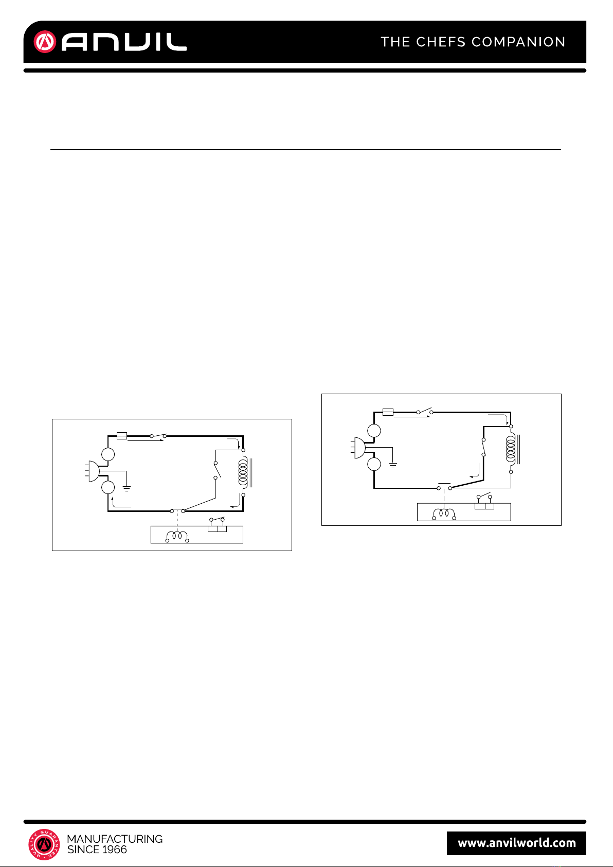
GENERAL DETAILS
• The low voltage transformer supplies the necessary
voltage to the micom controller when power cord is
plugged in.
• When the door is closed, the primary switch is ON, the
secondary switch is ON, and the monitor switch opens
(contact COM and NO).
WHEN SELECTING COOKING POWER
LEVEL AND TIME
• The micom controller memorizes the function you set.
• The time you set appears in the display window.
• Each indicator light turns on to indicate that the stage
has been set.
WHEN TOUCHING THE START PAD
• The coil of the relay is energized by the micom
controller.
• Power input is supplied to the high voltage transformer
through the fuse to the primary switch and relay 2.
• Turntable rotates.
• The fan motor rotates and cools the magnetron by
blowing the air (coming from the intake on the
baseplate)
• The air is also directed into the oven to exhaust the
vapor in the oven through the upper plate.
• Cooking time starts counting down.
• 3.2 volts AC is generated from the filament winding of
the high voltage transformer. This 3.2 volts is applied
to the magnetron to heat the magnetron filament
through two noise preventing choke coils.
• A high voltage of approximately 2100 volts AC is
generated in the secondary of the high voltage
transformer which is increased by the action of the high
voltage diode and charging of the high voltage
capacitor.
• The negative 4,000 Volts DC is applied to the filament
of the magnetron.
WHEN THE OVEN IS SET AT ANY LEVEL
EXCEPT MAXIMUM.
• The micom controller controls the ON-OFF time of relay
2 by the applied signal to vary the average output
power of microwave oven as POWER LEVEL.
(refer to page 1-1)
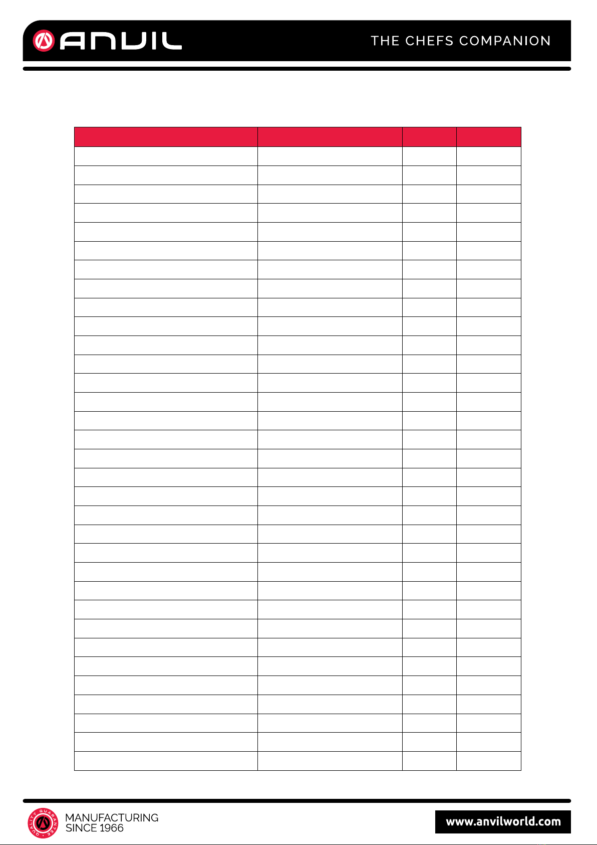
WHEN THE DOOR IS OPENED DURING
COOKING
• Both the primary switch and relay 2 are cut o ffprimary
winding voltage of the high voltage transformer.
• ON-OFF of relay 2 is coupled electrically with opening
and closing of the secondary switch.
• When the door is opened, the secondary switch is
opened and when the door is closed, the secondary
switch is closed.
• The cooking time stops counting down.
• Relay stops functioning.
• As the door is opened, if the contact of primary switch
and relay 2 and/or secondary switch fails to open, the
fuse opens due to the large current surge caused by
the monitor switch activation, which in turn stops
magnetron oscillation.
L
FUSE
TRANS-
FORMER
RELAY 2
MICOM CONTROLLER
SECONDARY
SWITCH
SWITCH
N
MONITOR
SWITCH
PRIMARY
MONITOR
SWITCH
L
FUSE
RELAY 2
MICOM CONTROLLER
SECONDARY
SWITCH
PRIMARY
SWITCH
N
CIRCUIT DESCRIPTION
TRANS-
FORMER
3
SERVICE INFORMATION
SERVICE INFORMATION
5
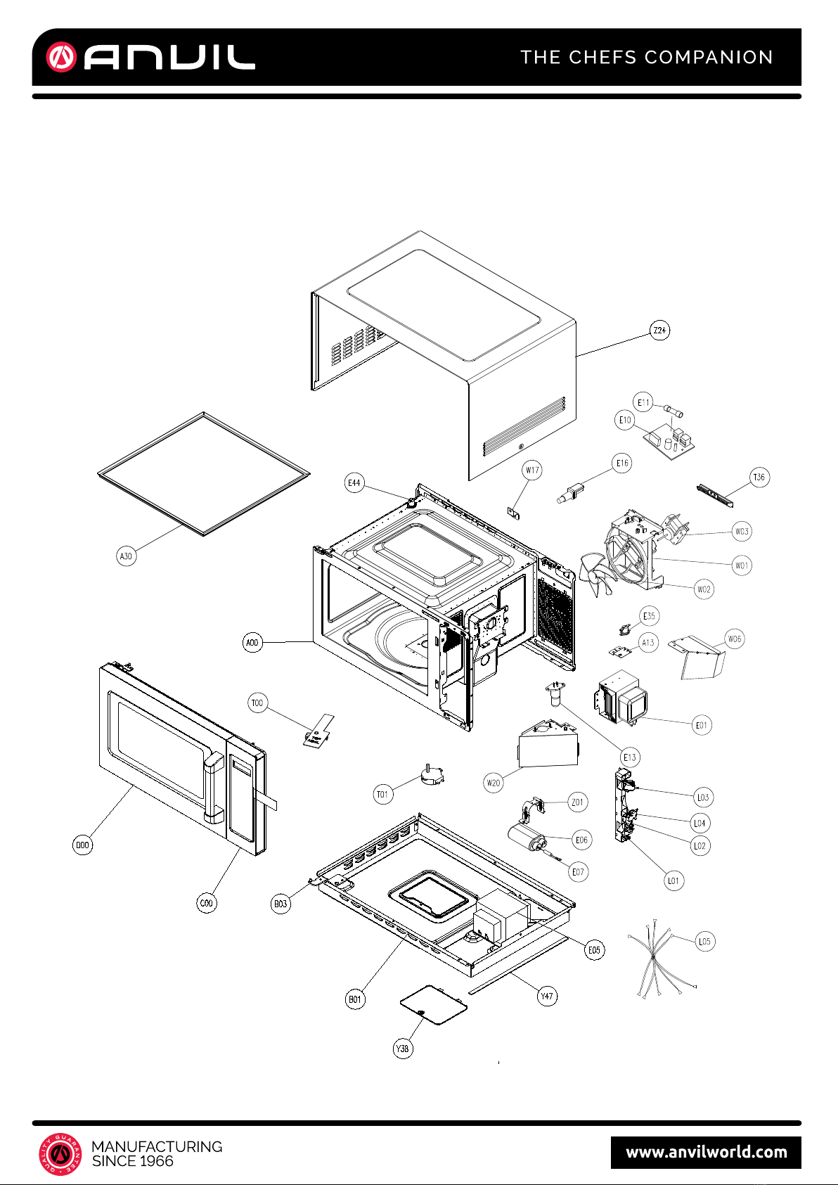
PARTS LIST
Part Code Part Name Qty/unit Positon
12270000000055 Cavity Assembly 1 A00
12270000008244 Thermostat Bracket 1 A13
12570000000005 Plate Cover *Inner Assembly 1 A30
12270000000005 Baseplate 1 B01
12270000006204 Hinge Assembly 1 B03
17270000B56728 + 17170000001145 Control Panel Assembly 1 C00
12170000002937 Control Panel 1 C01
12270000004436 C/Panel Decoration 1 C02
17170000022997 Mi Assembly 1 C18
17170000001145 Membrane Switch 1 C17
12670000000009 Sealing Ring 1 C50
12270000B60274 + 12570000000410 Door Assembly 1 D00
12270000003760 Door Frame Assembly 1 D01
12170000003856 Latch 1 D02
12970000000365 Latch Spring 1 D03
12270000006147 Hinge 1 D04
12170000009513 Door Film 1 D05
12570000000410 Glass Door Screen 1 D06
12170000A31661 Door Panel Assembly 1 D07+D09
12170000009562 Door Gasket 1 D08
12970000000563 Handle Assembly 1 D14
17470000002377 Magnetron 1 E01
17470000007043 H.V.Transformer 1 E05
17470000006823 H.V.Capacitor 1 E06
17470000001016 H.V.Diode 1 E07
17170000004586 Noise Fliter 1 E10
17470000005683 Fuse 1 E11
17470000009104 Integrated Lamp 1 E13
17470000000231 Power Cord 1 E16
17470000009127 Thermostat 1 E35
17470000001481 Thermostat 1 E44
12170000003401 Latch Board 1 L01
12170000007318 Interlock Lever 1 L02
6
Part Code Part Name Qty/unit Positon
17470000002294 Microswitch 2 L03
17470000002313 Microswitch 1 L04
17470000002444 Main Wire Harness 1 L05
12270000010792 Stirrer Fan Assembly 1 T00
11002014000013 Synchronous Motor 1 T01
12170000003988 Sealing Water Bracket 1 T36
12170000004303 Fan Guide 1 W01
12170000000209 Fan 1 W02
11002017001305 Brushless DC Motor 1 W03
12270000000150 Wind Guide Cover 1 W06
12270000033201 MOUNTING PLATE 1 W17
12270000000158 Wind Guide Cover 1 W20
12270000000176 Lamp Shade 1 Y38
12270000006211 Capacitor Holder 1 Z01
12270000005872 Cover 1 Z24
PARTS LIST
7
E
D
C
B
3 4
4 5
2 5 6 7
32 6 7
8
81
1
A
F
E
D
C
B
A
9 10 11 12
9 10 11 12
G
H H
G
F
J
K
L
M
L
K
J
M
13 14 15 16
13 14 15 16
PARTS DIAGRAM
8
E
D
C
B
3 4
4 5
2 5 6 7
32 6 7
8
81
1
A
F
E
D
C
B
A
9 10 11 12
9 10 11 12
G
HH
G
F
J
K
L
M
L
K
J
M
13 14 15 16
13 14 15 16
E
D
C
B
3 4
4 5
2 5 6 7
32 6 7
8
81
1
A
F
E
D
C
B
A
9 10 11 12
9 10 11 12
G
HH
G
F
J
K
L
M
L
K
J
M
13 14 15 16
13 14 15 16
PARTS DIAGRAM
Other manuals for MWA1400
1
Table of contents
Other Anvil Microwave Oven manuals


M Service manual")


