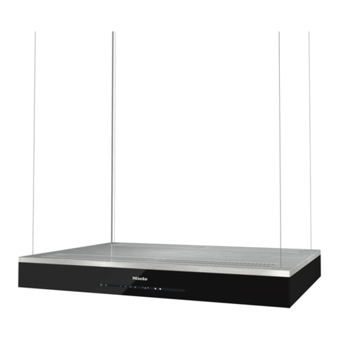
Ancona UC PRO Turbo 30 User manual

IMPORTANT SAFETY INSTRUCTIONS
Carefully read the following important information regarding
installation safety and maintenance.
Keep these instructions for future reference.
07/08/2017
UC PRO Turbo 30, 36
MAAN1287-02

Important Safety Notice
Read all Instructions before Installing and operating this appliance
The installation in this manual is intended for qualified installers, service technicians or persons with•
similar qualified background. Installation and electrical wiring must be done by qualified profession-
als and in accordance with all applicable codes and standards, including fire-rated construction.
DO NOT• attempt to install this appliance yourself. Injury could result from installing the unit due to
lack of appropriate electrical and technical background.
Range hood may have very sharp edges; please wear protective gloves if it is necessary to remove any•
parts for installing, cleaning or servicing.
Activating any switch ON before completing installation may cause ignition or an explosion.•
Due to the size and weight of this range hood, two people installation is recommended.•
To reduce the risk of fire, electric shock, or injury to persons:
For general ventilating use only. • DO NOT use to exhaust hazardous or explosive materials and va-
pors.
The combustion air flow needed for safe operation of fuel-burning equipment may be affected by this•
unit’s operation. Follow the heating equipment manufacturer’s guideline and safety standards such
as those published by the National Fire Protection Association (NFPA), and the American Society of
Heating, Refrigeration and Air Conditioning Engineers (ASHRAE), and the local code authorities.
Before servicing or cleaning unit, switch power OFF at service panel and lock service panel to pre-•
vent power from being switched ON accidentally.
Clean grease laden surfaces frequently. To reduce the risk of fire and to disperse air properly, make•
sure to vent air outside. DO NOT vent exhaust into spaces between walls, crawl spaces, ceiling, attics
or garages.
Ducted fans MUST always be vented to the outdoors.•
Use only metal ductwork and this unit MUST be grounded.•
Sufficient air is needed for proper combustion and exhausting of gases through the duct to prevent•
back drafting.
When cutting or drilling into wall or ceiling, be careful not to damage electrical wiring or other hid-•
den utilities.
All electrical wiring must be properly installed, insulated and grounded.•
Old duct work should be cleaned or replaced if necessary to avoid the possibility of a grease fire.•
Check all joints on duct work to insure proper connection and all joints should be properly taped.•
Use this unit only in the manner intended by the manufacturer. If you have questions, contact the•
vendor.
To reduce the risk of a stove top grease fire:
Keep all fan, baffle, spaces, filter, grease tunnel, oil container and grease-laden surfaces clean. Grease•
should not be allowed to accumulate on fan, baffle, spaces, filter, grease tunnel and oil container.
Always turn range hood ON when cooking at high heat or when cooking flaming foods.•
Use high settings on cooking range only when necessary.•
Never leave surface units unattended at high settings. Boil overs cause smoking and greasy spillovers•
that may ignite. Heat oils slowly on low or medium settings. Page 1

Page 2
Your safety and the safety of others is very important. We have provided many important safety mes-
sages in this manual and on your appliance. Always read and obey all safety messages. All safety mes-
sages will tell you what the potential hazard is, tell you how to reduce the chance of injury, and tell you
what can happen if the instructions are not followed.
This is the safety alert symbol. This symbol alerts you to potential hazards that can hurt you and others.
All safety messages will follow the safety alert symbol and the word “WARNING”.
WARNING
Clean ventilating fan frequently.•
Always use appropriate cookware and utensils size.•
Always use cookware appropriate for the size of the surface element.•
To reduce the risk of injury to persons in the event of a stove top grease fire:
SMOTHER FLAMES with a close-fitting lid, cookie sheet, or metal tray, then turn OFF the burner.•
BECAREFUL TO PREVENT BURNS. NEVER PICK UP A FLAMING PAN—you may be burned.
KEEP FLAMMABLE OR COMBUSTIBLE MATERIAL AWAY FROM FLAMES. If the flames DO
NOT go out immediately, EVACUATE AND CALL THE FIRE DEPARTMENT or 911.
DO NOT USE WATER, including wet dishcloths or towels — a violent steam explosion will result.•
Use an extinguisher ONLY if:•
You know you have a Class A, B, C extinguisher, and you already know how to operate it.•
The fire is small and contained in the area where it is started.•
The fire department is being called.•
You can fight the fire with your back to an exit.•
To reduce the risk of injury to persons in the event of a gas leaks:
Extinguish any open flame.•
DO NOT turn on the lights or any type of appliance.•
Open all doors and windows to disperse the gas. If you still smell gas, call the gas company and fire•
department, or 911 immediately.
Important Safety Notice
Read all Instructions before Installing and operating this appliance

Table of Contents
INSTALLATION
Tools needed....................................................3
Parts supplied...................................................4
Venting requirements.......................................5
Mount heights & clearance...........................5-6
Calculating vent system length.......................6
Venting methods..............................................7
Electrical requirements....................................8
Preparation......................................................9
Installation................................................10-11
Range hood operations.............................12-13
USE AND CARE
Troubleshooting...........................................14
Use and care information...............................15
Specifications..............................................15
Measurements & Diagrams......................16-22
MAINTENANCE
Cleaning.................................................23
Replacing the filter & light bulb.....................23
WARRANTY
Coverage & exceptions..................................24
Tools needed:
Page 3
Level
Flat-blade
and Phillips
screwdrivers
Powered
screwdriver
or drill
Measuring
tape
Utility knife
Marker or
pencil

Page 4
Under Cabinet Range Hood
Parts supplied:
Baffle Filters
Baffle Filter Spacer
Grease Tunnel
Fil
ter Space
r
Gr
ease Tunne
l
Qty: 4 PCS
(For sheet rock only)
Qty: 4 PCS
Qty: 8 PCS
Hood-mounting Bracket (Qty: 2PCS)
Ducting Transition
Qty: 8 PCS
Qty: 8 PCS
Qty: 10 PCS
(Round head)
Qty: 8 PCS
(Flat head)
Optional for
Single-piece
Chimney
Single-piece Chimney
(Optional)

Ceiling
Height
Venting Requirements
Page 5
Height & Clearance
Under Cabinet
Range hood
36”
Counter
Top
Min:
27”
Max: 30”
Vent system must terminate to the outside•
(roof or side wall).
DO NOT terminate the vent system in an at-•
tic or other enclosed area.
DO NOT use 4” (10.2 cm) laundry-type wall•
caps.
Use metal/aluminum vent only. Rigid metal/•
aluminum vent is recommended.
DO NOT use plastic vent.•
Always keep the duct clean to ensure proper•
airflow.
Calculate the following figures before instal-•
lation:
Distance from the floor to the ceiling.1.
Distance between the floor to the coun-2.
tertop/stove (recommend* 27” to 30”).
Distance between the countertop/stove3.
to the range hood.
Height of hood and duct cover.4.
For the most efficient & quiet operation:
A distance of 27” to 30” is recommended*•
between stove top and the bottom of range
hood.
•It is recommended that the range hood be
vented vertically through the roof through
8” (20.3 cm) or bigger round metal/
aluminum vent work.
The size of the vent should be uniform.•
Use no more than three 90° elbows.•
Make sure there is a minimum of 24” (61•
cm) of straight vent between the elbows if
more than one elbow is used.
DO NOT install two elbows together.•
The length of vent system and number of•
elbows should be kept to a minimum to pro-
vide efficient performance.
The vent system must have a damper. If•
roof or wall cap has a damper, DO NOT
use damper (if supplied) on top of the range
hood.
Use silver tape or duct tape to seal all joints•
in the vent system.
Use caulking to seal exterior wall or roof•
opening around the cap.
* Due to different ceiling height configurations, rec-
ommended height may not be applicable.
Cabinet or Single-
piece Chimney
(Optional)
Range
Hood
Height
Cabinet
Height
Countertop/Stove

Page 6
IMPORTANT:
A minimum of 8” round (standard for this range hood) or 3-1/4 x 10” rectangular duct (purchased separate-•
ly) must be used to maintain maximum airflow efficiency.
Always use rigid type metal/aluminum ducts if available to maximize airflow when connecting to provided•
duct.
Please use • Duct Run Calculation below to compute total available duct run when using elbows, transitions
and caps.
ALWAYS, when possible, reduce the number or transitions and turns. If long duct run is required, increase•
duct size from 8” to 9” or 10”. If a reducer is used, install a long reducer instead of a pancake reducer. Re-
ducing duct size will restrict airflow and decrease airflow, thus reduce duct size as far away from opening as
possible.
If turns or transitions are required: Install as far away from opening and as far apart, between 2, as possible.•
Minimum mount height between stove top to hood bottom should be no less than 27-inch*.•
Maximum mount height between stove top to hood bottom should be no higher than 30-inch*.•
It is important to install the hood at the proper mounting height. Hoods mounted too low could result in heat•
damage and fire hazard; while hoods mounted too high will be hard to reach and will loose its performance
and efficiency.
If available, also refer to stove top manufacturer’s height clearance requirements and recommended hood•
mounting height above range.
* Due to different ceiling height configurations, recommended height may not be applicable.
Minimum Duct Size:
Round - 8” minimum•
Rectangular - 3-1/4 x 10” minimum (requires a 8” to 3-1/4x10” adaptor, not supplied)•
Duct Run Calculation:
Recommended maximum run
8” or 3-1/4 x 10” duct 50 ft
Vent piece deduction
Each 90º elbow used 9 ft
Each 45º elbow used 5 ft
Each 8” to 3/14 x 10” transition used 7 ft
Side wall cap with damper 0 ft
Roof cap 0 ft
Duct Run Calculation example:
One roof cap, two 90º elbow, and one 45º elbow used:
0ft + 9ft + 9ft + 5ft = 23ft used.
Deduct 23ft from 50ft, 27ft maximum available for
straight duct run.
Calculating Vent System Length
To calculate the length of the system you need, deduct the equivalent feet for each vent piece used in the system
from the recommended maximum duct run.

Venting Methods
Page 7
This range hood is factory set for venting through the roof or wall.•
Vent work can terminate either through the roof or wall. To vent through a wall, a 90° elbow is needed.•
IMPORTANT:
NEVER exhaust air or terminate duct work into spaces between walls, crawl spaces, ceiling, attics or•
garages. All exhaust must be ducted to the outside.
Use metal/aluminum duct work only.•
Fasten all connections with sheet metal screws and tape all joints with certified Silver Tape or Duct Tape.•
Use caulking to seal exterior wall or roof opening around the cap.•
Vertical roof venting
Roof cap
Option 2:
Side wall cap
Horizontal wall venting
Option 1:

IMPORTANT: Observe all governing codes and ordinances.
It is the customer’s responsibility:
To contact a qualified electrical installer.•
If codes permit and a separate ground wire is used, it is recommended that a qualified electrician determine that
the ground path is adequate.
A 120-Volt, 60 Hz, AC-only, fused electrical supply is required on a separate 15-amp circuit, fused on both sides
of the line.
DO NOT ground to a gas pipe.
Check with a qualified electrician if you are not sure that the range hood is properly grounded.
DO NOT have a fuse in the neutral or ground circuit.
IMPORTANT: Save this Installation Guide for electrical inspector’s use.
The range hood must be connected with copper wire/plug only.
The range hood should be connected directly to the fused disconnect (or circuit breaker) box through flexible
armored or non-metallic sheathed copper cable.ETL - listed strain relief must be provided at each
end of the power supply cable.
Wire sizes (copper wire only) and connections must conform with the rating of the appliance as specified on
the model/serial rating label. Wire sizes must conform to the requirements of the National Electrical Code
ETL. - listed conduit con-
nector must be provided at each end of the power supply cable (at the range hood and at the junction box).
Page 8
Electrical Requirements

Preparation
Page 9
Advanced Preparations:
Be familiar with the controls of the range hood by reading•
through Range Hood Operations, Page 12.
•Place the range hood on a flat, stable surface. Connect the
range hood to a designated standard outlet (120-Volt, 60Hz,
AC only) and turn on the range hood. Verify all operations
of the range hood by referring to Range Hood Operations,
Page 12.
Place all supplied parts and required hardware on a flat, stable surface and verify•
the existence of all supplied parts listed on Page 4.
Carefully remove the white plastic protective coat from the range hood.•
Preparations:
NOTE: To avoid damage to your hood, prevent debris from entering the vent opening.
Decide the location of the venting pipe from the hood to the outside. Refer to • Venting Methods on Page 7.
A straight, short vent run will allow the hood to perform more efficiently.•
Try to avoid as many transitions, elbows, and long run as possible. This may reduce the performance of the•
hood.
IMPORTANT: Peel white plastic protective coat off the hood, if any.•
Use silver tape or duct tape to seal joints between pipe sections.•
For installing under the cabinet with recessed bottom, attach 4-inch wide wood filler strips (not provided) on•
each side. Refer to Figure 1.
Using references in •Measurements and Diagrams on Page 16, create access opening for electrical wires and
hood exhaust under the cabinet.
CAUTION: If moving the cooking range is necessary to install the hood, turn OFF the power on an elec-
tric range at the main electrical box. SHUT OFF THE GAS BEFORE MOVING A GAS RANGE.
Puncture the knockout holes (for mounting under the cabinet) on the hood as shown in Figure 2.•
If necessary, attach two rubber stands with 3M adhesive tapes to the back corners of the hood.•
Attach ducting transition to hood exhaust with included 10 round head screws as shown in Figure 3.•
Excessive Weight
Require three or more person to move and
install this range hood. Spinal or other bodi-
ly injuries could occur if it is not followed.
WARNING
Severe Injury
Rotating fan can cause severe
injury. Stay clear of fan when
motor is running.
WARNING
Figure 1 Figure 2 Figure 3
This manual suits for next models
1
Table of contents
Other Ancona Ventilation Hood manuals

Ancona
Ancona Elite IGCE636 Manual

Ancona
Ancona GCB630 Manual

Ancona
Ancona WPL636 User manual

Ancona
Ancona GCC430 Manual

Ancona
Ancona WPD430 User manual

Ancona
Ancona WPNL630 User manual

Ancona
Ancona B328 User manual

Ancona
Ancona WPRL430 Manual

Ancona
Ancona gc430 User manual

Ancona
Ancona TORNADO ISLAND II 36 User manual