Ametek Magnetrol SOLITEL User manual
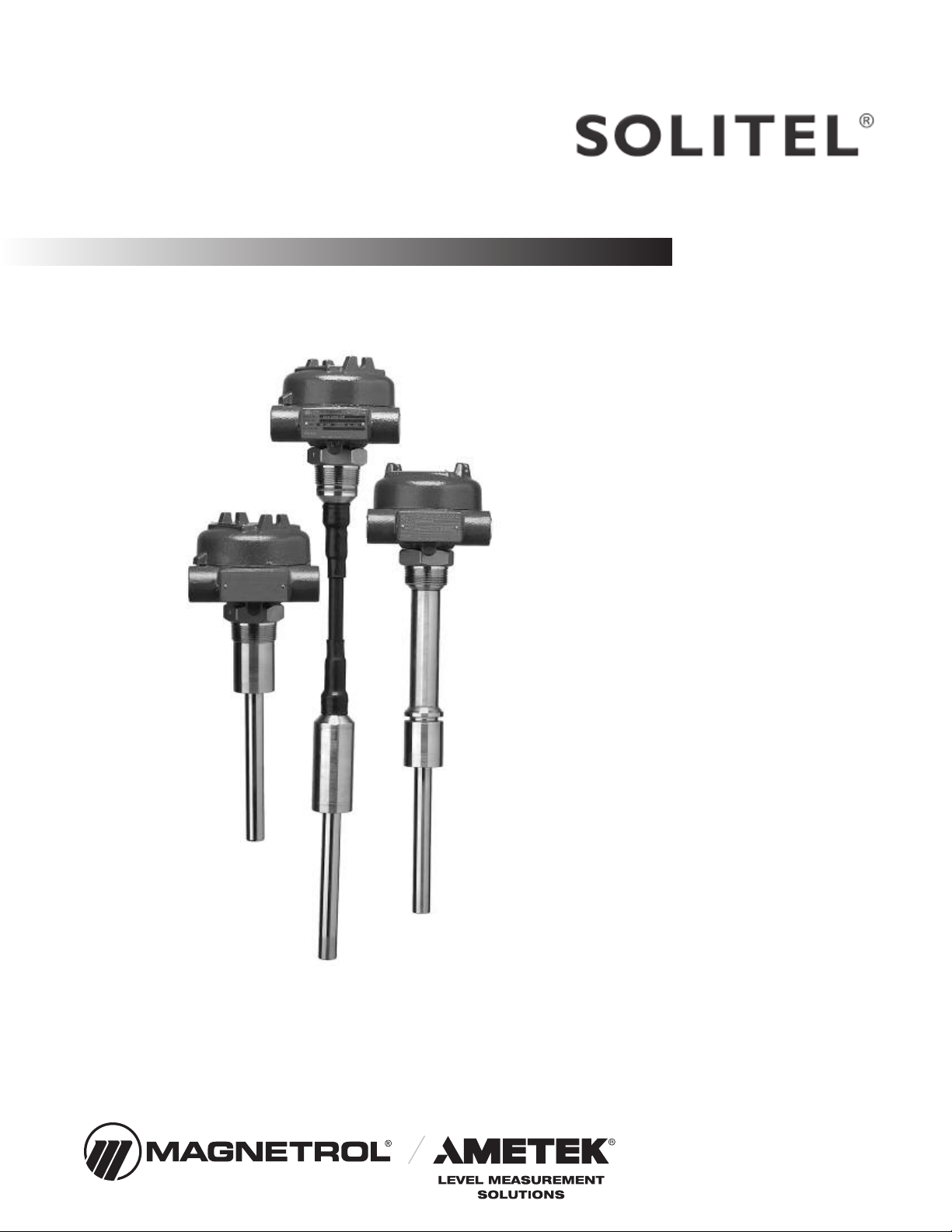
Installation and Operating Manual
Solitel
Vibrating
Rod Level
Switch

Read this Manual Befo e Installing
This manual provides information on the Solitel®
Vibrating Rod Level Switch. It is important that all
instructions are read carefully and followed in sequence.
Detailed instructions are included in the Complete
Installation section of this manual.
Conventions Used in this Manual
Certain conventions are used in this manual to convey
specific types of information. General technical material,
support data, and safety information are presented in
narrative form. The following styles are used for notes,
cautions, and warnings.
Notes
Notes contain information that augments or clarifies
an operating step. Notes do not normally contain
actions. They follow the procedural steps to which
they refer.
Cautions
Cautions alert the technician to special conditions that
could injure personnel, damage equipment, or reduce
a component’s mechanical integrity. Cautions are also
used to alert the technician to unsafe practices or the
need for special protective equipment or specific
materials. In this manual, a caution box indicates a
potentially hazardous situation which, if not avoided,
may result in minor or moderate injury.
Wa nings
Warnings identify potentially dangerous situations or
serious hazards. In this manual, a warning indicates an
imminently hazardous situation which, if not avoided,
could result in serious injury or death.
Safety Messages
The Solitel system is rated by the IEC for use in Category
II, Pollution Degree 2 installations. Follow all standard
industry procedures for servicing electrical and computer
equipment when working with or around high voltage.
Always shut off the power supply before touching any
components. Although high voltage is not present in this
system, it may be present in other systems.
Electrical components are sensitive to electrostatic
discharge. To prevent equipment damage, observe safety
procedures when working with electrostatic sensitive
components.
This device complies with Part 15 of the FCC rules.
Operation is subject to the following two conditions: (1)
This device may not cause harmful interference, and (2)
This device must accept any interference received, includ-
ing interference that may cause undesirable operation.
Low Voltage Di ective
For use in Category II installations. If equipment is used
in a manner not specified by manufacturer, protection
provided by equipment may be impaired.
WARNING! Explosion hazard. Do not connect or
disconnect equipment unless power has been switched off
or the area is known to be non-hazardous.
Wa anty
All Magnetrol electronic level and flow controls ar
warranted free of defects in materials or workmanship
for eighteen months from the date of original factory
shipment.
If returned within the warranty period; and, upon
factory inspection of the control, the cause of the
claim is determined to be covered under the warranty;
then, Magnetrol will repair or replace the control at no
cost to the purchaser (or owner) other than transporta-
tion.
Magnetrol shall not be liable for misapplication, labor
claims, direct or consequential damage or expense arising
from the installation or use of equipment. There are no
other warranties expressed or implied, except special writ-
ten warranties covering some Magnetrol products.
Quality Assu ance
The quality assurance system in place at Magnetrol
guarantees the highest level of quality throughout the
company. Magnetrol is committed to providing full
customer satisfaction both in quality products and
quality service.
The Magnetrol quality assurance system is registered to
ISO 9001 affirming its commitment to known
international quality standards providing the strongest
assurance of product/service quality available.
Copyright © 2022 AMETEK Magnetrol USA, LLC.
All rights reserved.
Performance specifications are effective with date of issue
and are subject to change without notice. Magnetrol®
reserves the right to make changes to the product
described in this manual at any time without notice.
Magnetrol makes no warranty with respect to the accura-
cy of the information in this manual.
1.0 Introduction
The Solitel®Vibrating Rod Level Switch provides reliable
level detection of bulk solids and powders. This compact,
integral switch is suitable for high or low level detection
in hoppers and silos. It may also be used for plugged
chute detection.
The rugged, single-piece probe is suitable for use in a
variety of powders or granular materials with a minimum
bulk density of less than one pound per cubic foot.
1.1 Principle of Operation
The Solitel®rod vibrates at a 350 Hz frequency. When
media makes contact with the rod, the vibration is damp-
ened. The attenuation of the vibration is detected by the
integral mount electronics, changing the status of the relay.
2.0 Installation
2.1 Unpacking
Unpack the instrument carefully. Make sure all compo-
nents have been removed from the packing material.
Inspect all components for damage, and report any
concealed damage to the carrier within 24 hours.
Check the contents of the carton, making sure it agrees
with the packing slip and the purchase order. Verify that
the model number imprinted on the nameplate matches
the number on the packing slip and the purchase order.
Report any discrepancies to the factory. Check and record
the serial number for future reference when ordering parts.
Serial Number
2.2 Mounting
Prior to installation, it is recommended that the unit be
calibrated using a sample of the media to be measured.
Refe to Calib ation, Section 2.5.
IMPORTANT: Handle the instrument with great care,
especially the probe. Any impact on the probe can damage
the vibration system.
3
56-601 Solitel Vibrating Rod Level Switch
Figure 1
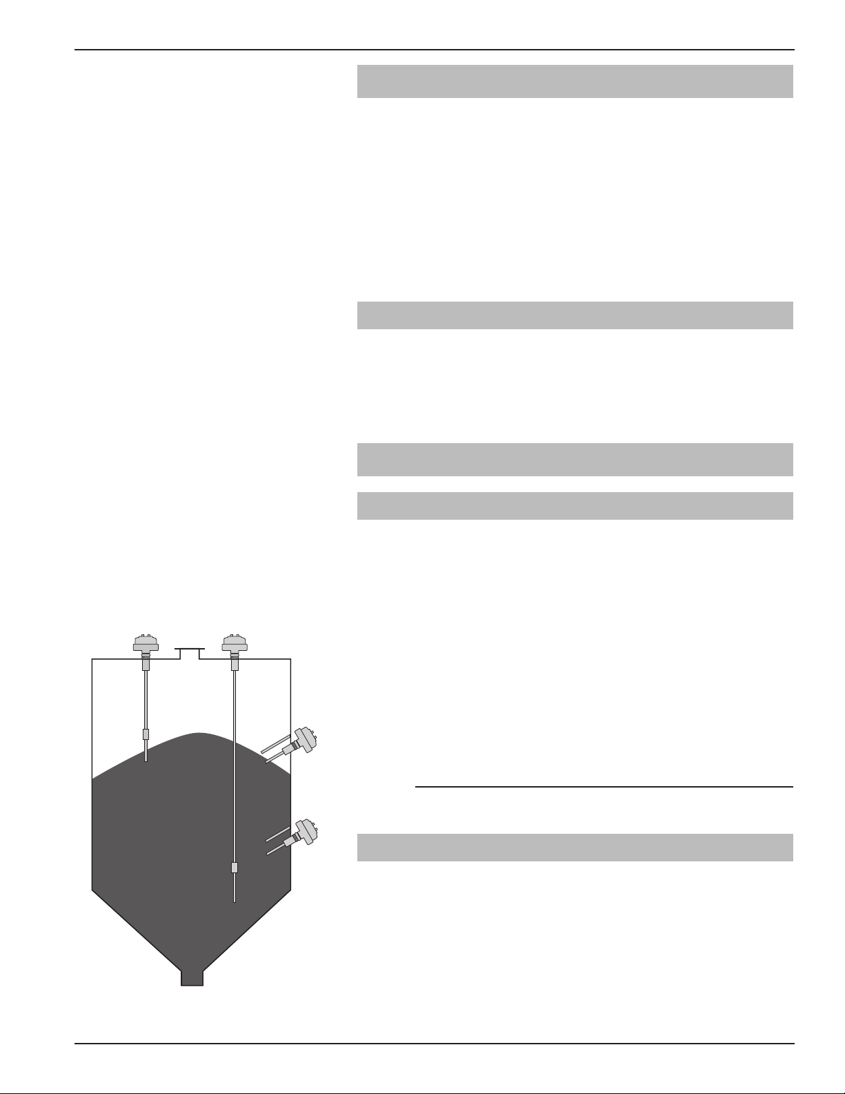
The SOLITEL switch is mounted to the vessel using a
11⁄2" NPT threaded connection.
• Ensure that the tip of the probe is located at the desired
switching point giving consideration to the slope angle of
the material.
• The switch may be installed vertically or horizontally
(at a downward angle) as shown in Figure 1 on page 3.
• Avoid mounting the sensor in a recess where buildup
could dampen the vibration. See Figure 2.
• Do not cut or bend the vibrating rod.
IMPORTANT: A deflection plate is required when the
probe is exposed to falling material, collapsed arch, or, in the
case of a low level switch, when the drag force of the empty-
ing material exceed the specifications. The deflector can be
a baffle plate or angle iron (11⁄2" ×11⁄2" ×1⁄8") located 4 to
6 inches above the rod. See Figure 3.
Observe the specifications for bending force(F),
torque(M), and pull force(F) as indicated below:
See Figure 4.
Standard: F = 100 pounds (445 N)
M = 63 foot pounds (85 Nm)
Extended Rigid: M = 63 foot pounds (85 Nm)
When using an extended length version for low level
alarm, mount the probe above the outlet of the vessel to
avoid the probe being dragged along by the outflowing
material.
2.3 Electrostatic Discharge (ESD)
Handling Procedure
MAGNETROL electronic instruments are manufactured
to the highest quality standards. These instruments utilize
electronic components which may be damaged by static
electricity present in most work environments. The
following steps are recommended to reduce the risk of
component failure due to electrostatic discharge:
1. Ship and store circuit boards in anti-static bags. If an
anti-static bag is not available, wrap board in aluminum
foil. Do not place boards on foam packing materials.
456-601 Solitel Vibrating Rod Level Switch
Figure 2
Figure 3
VXH VXR VXK
F
M
F
M
Figure 4
2. Use a grounding wrist strap when installing and
removing circuit boards. A grounded workstation is
also recommended.
3. Handle printed circuit boards only by the edges. Do not
touch components or connector pins.
4. Ensure that all electrical connections are completely made
and none are partial or floating. Ground all equipment to
a good earth ground wiring.
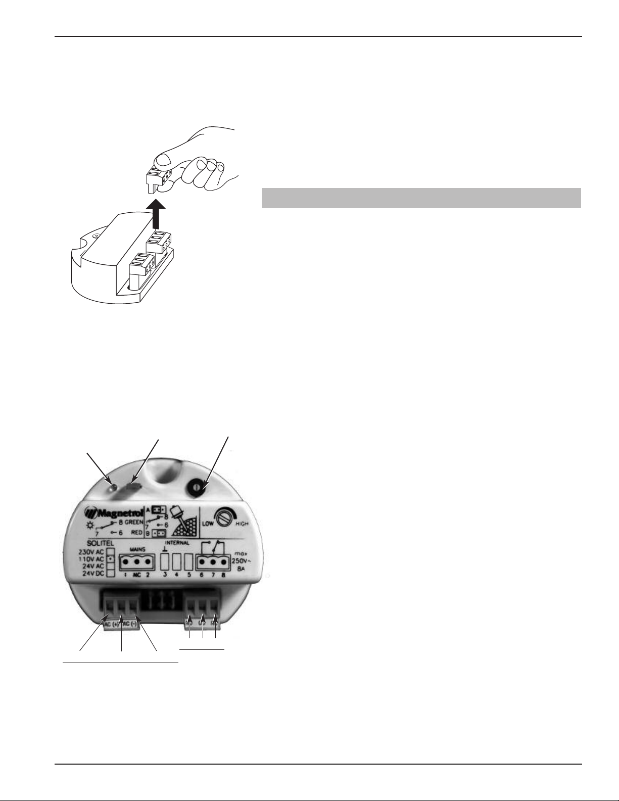
2.4 Wiring
Manually position the housing in the correct direction to
allow for easy wiring. The housing can rotate one full turn.
1. Make sure the power supply is turned off.
2. Unscrew and remove housing cover.
3. Connect power leads to the proper terminals. To simplify
wiring, the terminal strips may be removed from the
module by lifting the front edge of the terminal block.
Refer to Figure 5.
a. 120 VAC – Connect the “hot” wire to terminal marked
L1 and the “neutral” to terminal L2/N. There is no con-
nection to the center terminal.
b. 24 VDC – Connect wires to terminals (+) and (-). There
is no connection to the center terminal.
4. To ensure optimum noise immunity, attach the ground
wire to the green grounding screw inside the housing base.
Caution: On 24 VDC units, the negative terminal of the power
supply is isolated from ground and proper earth grounding
of the power supply shield wire is necessary for noise
immunity.
5. Connect relay terminals. Refer to Figure 6.
6. Set the fail-safe jumper as described in the table on page 6.
For alarm applications, it is recommended that the
de-energized status of the relay be used as the alarm status.
This allows detection of power failure as an alarm status.
7. Wiring is complete. Replace the housing cover.
8. Apply power to the unit.
5
56-601 Solitel Vibrating Rod Level Switch
Figure 6
L1(+) No Connection L2/N(-)
Power
LED
Fail safe jumper
Sensitivity
adjustment
NO CO NC
Relay
Figure 5

2.5 Calibration
Ensure that the fail-safe jumper is installed in the proper
position as described in Table 1. The LED will show
red when in alarm condition and green when in normal
condition. Test the operation of the switch by holding,
and then releasing the vibrating rod; the LED will
change color.
The sensitivity of the switch can be changed using the
density adjustment screw. Note that this adjustment screw
has 270 degrees of rotation. Do not rotate past the stops.
NOTE: If the adjustment is too sensitive, the switch may detect
even slight residue of material rather than level.
Prior to installation, it is recommended that the unit be
calibrated using a sample of the media to be measured.
656-601 Solitel Vibrating Rod Level Switch
Power Material Level Fail-Safe Jumper LED Color Relay Coil Relay Terminal
NO to CO NC to CO
6–7 7–8
On High A position Green De-energized Open Closed
B position Red Energized Closed Open
On Low A position Red Energized Closed Open
B position Green De-energized Open Closed
Fail High/Low A/B De-energized Open Closed
3.0 Reference Information
3.1 Troubleshooting
SOLITEL is a simple and reliable device. However, care
must be taken to avoid impacting or damaging the vibrat-
ing probe.
In the event the SOLITEL stops vibrating, the following
procedure will identify if the problem is with the electron-
ic module or with the sensor:
Disconnect the wires going to the sensor. (Terminals 3, 4,
and 5). The following gives the expected voltage range
between the sensors.
If these voltage readings are not obtained, the electronics
are defective and need to be replaced. If these voltages are
measured, the problem is with the sensor.
NOTE: The probe and electronics must be matched to ensure
proper operation. Use the following procedure to match
the electronics and the vibrating probe:
1. Connect the wires from the sensor to terminals 3, 4, 5.
There will be two wires of the same color and one wire of
different color. The two similar wires go to terminals 4 and
5; the single wire goes to terminal 3.
2. If the potentiometer is labeled “density” turn to the low
position – if labeled “sensitivity” turn to the high position.
Note this potentiometer has a 270 degree turn.
3. Apply power to the electronic module.
4. Turn the electronic module over.
7
56-601 Solitel Vibrating Rod Level Switch
Terminals Voltage
3 and 4 4 to 6 VDC
3 and 5 0.3 to 1.0 VAC
Figure 7
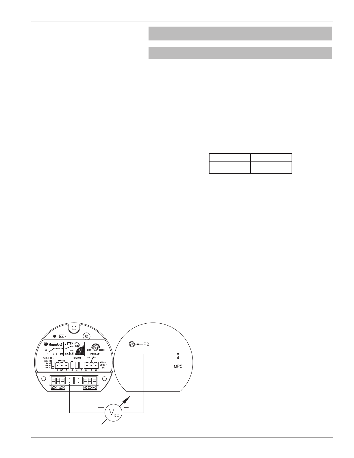
Front Rear
5. Connect a digital multimeter between points MP5 on the
back of the module and ground connection (terminal 3 on
the electronic module) or the body of the vibrating probe.
See Figure 7 on page 7.
6. Adjust potentiometer P2 on the rear of the electronic mod-
ule to obtain a voltage between 0.4 volts and 1.0 volts. The
reading should be as close to 1.0 volt as possible.
7. Grasp the vibrating section of the sensor with your hand.
The vibration should stop and the relay will change state.
8. Remove your hand from the sensor. The relay will
change state.
9. The electronic module and probe are now matched.
3.2 Agency Approvals
3.2.1 CSA
Model Approval
VXX-D1BX-XXX Class I, Div. 2
Groups A, B, C, & D
Class II, Div. 1
Groups E, F, & G
Type 4X
3.3 Replacement Parts
Item Description Part Number
1 Base 004-9189-001
2 Cover 004-9105-001
3 Cover o-ring 012-2101-345
4 Electronics module:
110 VAC Z30-9011-001
24 VDC Z30-9011-004
5 Bracket 005-6680-001
6 Probe o-ring 012-2408-001
7 Snap ring 010-5138-001
8 Sleeve 004-0111-001
9 Probe Consult Factory
856-601 Solitel Vibrating Rod Level Switch
These units have been tested to EN 50081-2
and EN 50082-2 and are in compliance with
the EMC Directive 89/336/EEC.
These units have been evaluated to the
applicable UL and CSA standards. CSA is
accredited as a NRTL (National Recognized
Testing Laboratory) in the United States.
NRTL/C
➁
➀
➂
➃
➄
➅
➆
➇
➈
3.4 Specifications
3.4.1 Performance
Description Specification
Input voltage 110 VAC +10/-15%
24 VDC (±10%)
Powe consumption Less than or equal to 3 VA
Ope ation f equency 350 Hz
Output elay SPDT 8 amp @ 250 VAC
SPDT 1 amp @ 24 VDC
Time delay 6–10 seconds
(depending on density adjustment)
P ocess connection 11⁄2" NPT
Housing NEMA 4X
Ope ating p ocess conditions
Standa d -4 to +230 F
(-20 to +110 C)
Enhanced pe fo mance -40 to +320 F
(-40 C to +160 C)
Ambient elect onics temp. -40 to +140 F, see chart at left
(-40 to +60 C)
Relative humidity 98%
Maximum p ocess p essu e 360 psig
Minimum Density 50 oz/ft3or 0.05 gm/cm3
Mate ials specifications
Vib ating od 316 stainless steel
Rigid extension 316 stainless steel
Inse tion length
VXH 8.25 inches (209 mm)
VXR 10 to 100 inches (25 to 254 cm)
Maximum mechanical load on p obe
St anded p obe 63 Ft/lbs. (85 Nm)
Extended igid p obe 63 Ft/lbs. (85 Nm)
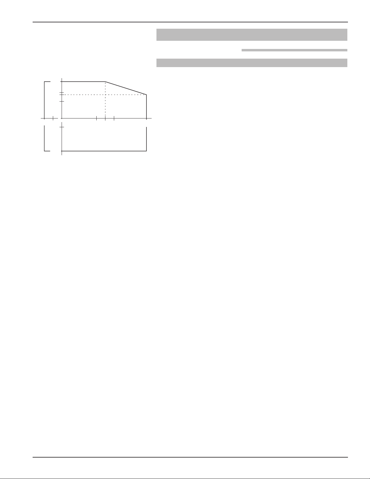
56-601 Solitel Vibrating Rod Level Switch
-40 F
(-40 C)
00
-40 F
(-40 C)
140 F
(60 C)
95 F
(35 C)
167 F
(75 C)
320 F
(160 C)
Process Temp.
Ambient Temp.
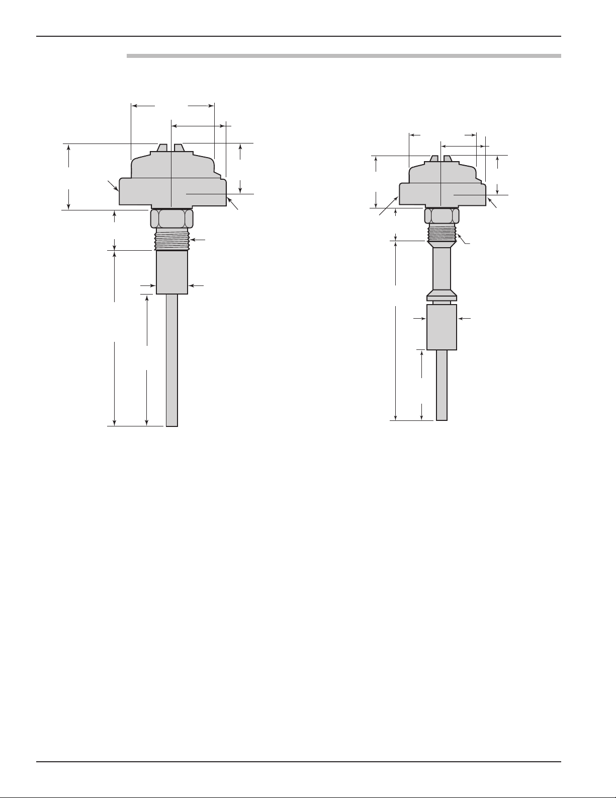
10 56-601 Solitel Vibrating Rod Level Switch
Standard Length
DIMENSIONAL SPECIFICATIONS inches (mm)
1.73 (44) Dia.
6.34
(161)
Insertion
length
8.25
(209)
3.44 (87)
Rotation clearance
11/2" NPT
process connection
3/4" NPT
Conduit connection
2.75
(69)
4.63
(117) Dia.
3.63
(92)
3/4" NPT
plugged
1.5
(38)
3.4.2 Physical
Extended Rigid Probe
1.73
(44) Dia
6.34
(161)
Insertion
length
11/2" NPT
process connection
3.44 (87)
Rotation
clearance
3/4" NPT
Conduit
connection
2.75 (69)
4.63
(117) Dia.
3.63
(92)
1.5
(38)
3/4" NPT
plugged
Table of contents
Other Ametek Switch manuals

Ametek
Ametek RFB 6000A User manual

Ametek
Ametek SIL IntelliPoint RF S*R*L Series User manual

Ametek
Ametek ThePoint Series User manual

Ametek
Ametek IntelliPoint RF RMT Series User manual

Ametek
Ametek Magnetrol Thermatel TD1 User manual

Ametek
Ametek Magnetrol3 Series User manual

Ametek
Ametek Magnetrol 3 Series User manual

Ametek
Ametek SWI L072 User manual

Ametek
Ametek Gemco 1950-4 User manual

Ametek
Ametek IntelliPoint RF RNT Series Assembly instructions


