Amate Audio NITID N208P User manual

User’s manual
December 2018

NITID N208 Dec 2018
2Amate Audio
Safety Instructions
1. All safety instructions must be read before using this device.
2. Keep and follow these instructions
3. Heed all warnings
4. The exclamation mark in the triangle indicates internal components which if
replaced can affect safety.
5. The lightning symbol within the triangle indicates the presence of dangerous
uninsulated voltages.
6. Only clean the device with a dry cloth.
7. Do not block any ventilation openings. Install in accordance with the
manufacturer’s instructions.
8. Do not install the device near heat sources such as radiators, heaters or other
heat-emitting elements.
9. Protect the power cord from being walked on or pinched, particularly at plugs,
convenience receptacles, and the point where they exit from the apparatus
10. The equipment must be repaired by qualified technical service personnel when:
A. The mains supply cable is damaged, or
B. Any object or liquid has damaged the device; or
C. The equipment does not function normally or correctly; or
D. The equipment has been exposed to the rain; or
E. The chassis is damaged
11. Disconnect the device in the case of electric storms or during long periods of
disuse.
12. WARNING – To reduce the risk of fire or electric shock, do not expose this
device to rain or moisture
13. The equipment shall not be exposed to dripping or splashing and no objects filled
with liquids, such as vases, shall be placed on the device.
14. For hanging and installation, use manufacturer recommended accessories only.
NITID N208 Dec 2018
3Amate Audio
1 INTRODUCTION
1.1 General
Amate Audio would like to thank you for your confidence in our NITID Series. We
suggest you to carefully read the following instructions in order to obtain the best
results in performance.
1.2 What is a line array?
The trend in sound reinforcement has been to increase both the sound pressure
level (SPL) and the size of the audience to be covered. This leads to an increase in
the number of cabinets and, as a result of this, an increase in the total size and
weight.
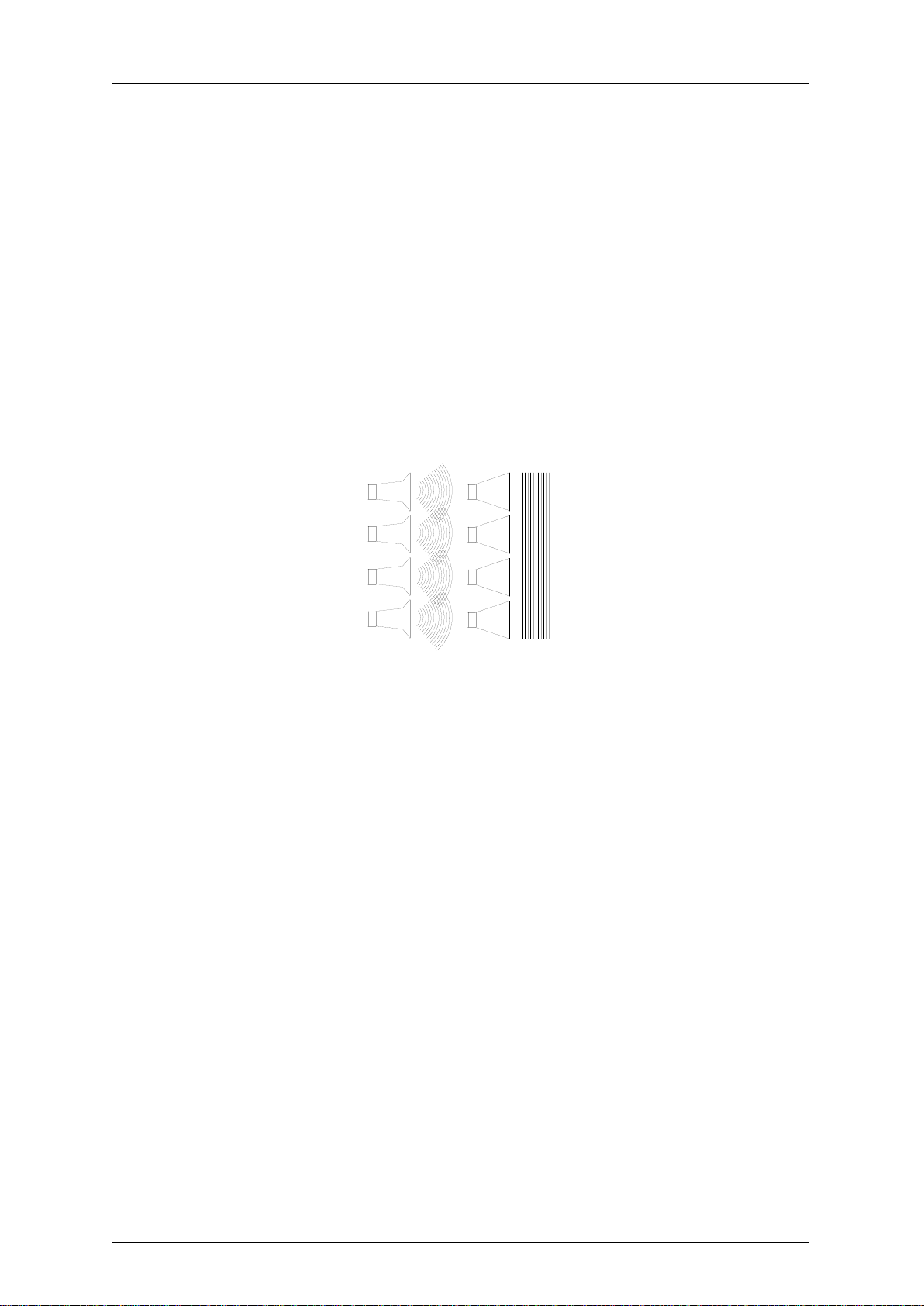
A line array is a group of independent sound sources which are vertically stacked in
order to transform the spherical wavefronts generated by individual sources into a
single flat wavefront.
Fig. 1. Wavefield interference for different wavefronts.
To carry out effectively arraying individual sound sources the system must follow the
acoustic coupling conditions based on the wavelength, the shape of each source, the
surface area of each transducer and the relative source separation.
An assembly of individual sound sources arrayed with regular separation between the
sources on a plane or curved continuous surface is equivalent to a single sound
source having the same dimensions as the total assembly if the following conditions
are fulfilled:
1) The step of source separation, defined as the distance between the acoustic
centres of the individual sources, is smaller than half the wavelength over the
bandwidth of operation.
d<= /2
It is not difficult to fulfil this first condition for the low and mid frequencies. For
example, two 7" loudspeakers that are separated by 17 cm will reproduce a cylindrical
wave up to 1015 Hz.
This condition is difficult to be fulfilled for the high frequencies, as their wavelengths
are too small to make the adjacent acoustic centres any smaller than /2. Here comes
the second "arrayability" criterion.

NITID N208 Dec 2018
4Amate Audio
2) The wavefronts generated by the individual sources are planar and the combined
surface area of the sources fills at least 80% of the total target surface area:
H1·W + H2·W+.....+Hn·W >=0.8·H·W
This is achieved by using waveguides, which are coupled to the compression drivers
output. We achieve flat wavefronts with a constant phase. By vertically assembling
these waveguides we fulfil the second criterion of line array construction.
Fig. 2. Second criterion of "arrayability"
3) The deviation from a flat wavefront must be less than λ/4 at the highest operating
frequency (this corresponds to less than 5 mm curvature at 16kHz).
This third condition can be
explained through our property
waveguide. Thanks to some
complex mathematical
calculations we have obtained a
component which is able to
adapt the circular section of the
compression driver to a
rectangular section, getting on-
phase waves at the end of the
guide. This flat wavefront is ideal
for vertical configurations.
Fig. 3. High frequency waveguide (half piece)
Sound engineers use line arrays to obtain narrow directivities on the vertical plane.
For configurations with many cabinets (big height) and at high frequencies it is not
unusual to achieve narrow angles- in some cases they may be grade fractions. This
NITID N208 Dec 2018
5Amate Audio
can be useful in venues where both a high sound pressure level and long throw are
required; nevertheless, this means less coverage of the audience area.
It is sometimes useful to achieve an asymmetrical coverage pattern on the vertical
plane, which can be obtained by aiming some of the cabinets through their hinging
points. We are now ready to define the last two criteria of "arrayability".
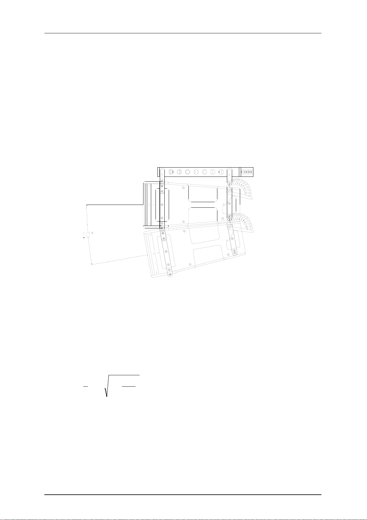
4) For curved arrays, the tilt angles should vary in inverse proportion to the listener
distance (this is geometrically equivalent to shaping variable curvature arrays to
provide equal spacing of individual element impact zones).
5) There are limits given the vertical size of each cabinet and their relative tilt angles.
In our case the maximum tilt angle (between cabinets) is 10º.
Fig. 4. Tilt angle between cabinets (10º maximum)
1.3 Fresnel Region (Near Field) and Fraunhofer Region (Far Field)
As our system is able to fulfil the previous conditions it will produce cylindrical waves
to a maximum frequency. The wave will be flat up to a certain distance where it will
start to become spherical (depending on the frequency and the size of the array).
The limit distance between the zone of cylindrical waves (Fresnel) and spherical
waves (Fraunhofer) can be calculated through the following formula
2
231
1
2
3
Hf
fHdc
where
dc= limit distance between near field and far field (in metres)
H = height of the array (in metres) f= frequency (in kHz)
In the near field region (Fresnel), the wavefront is cylindrical and waves only expand
on the horizontal plane (110º in N208). The height of the wavefront is, in this case,
the total height of the array.

NITID N208 Dec 2018
6Amate Audio
In the far field region (Fraunhofer), the wavefront is spherical and expands both on
the horizontal and vertical planes. The horizontal coverage is 110º and the vertical
coverage is defined by the frequency and the height of the array.
Fig. 5. Limits of Fresnel-Fraunhofer Regions
We can create a chart with some of the basic configurations and their performance
regarding wave propagation.
Frec
(Hz)
4x
N208
dc(m)
8x
N208
dc(m)
12x
N208
dc(m)
16x
N208
dc(m)
100
Esférica
Esférica
Esférica
1.3
125
Esférica
Esférica
0.7
2.2
250
Esférica
1.1
3
5.6
500
0.5
2.8
6.6
11.8
1k
1.4
5.9
13.3
23.8
2k
2.9
11.9
26.8
47.9
4k
5.9
23.9
54
95.9
8k
11.9
47.9
107.9
191.9
10k
14.9
59.9
134.9
239.8
Fig. 6. dcCalculation
An 8-cabinet array has a near field extending to 12 metres at 2kHz. Beyond this
distance the wavefront will be spherical.
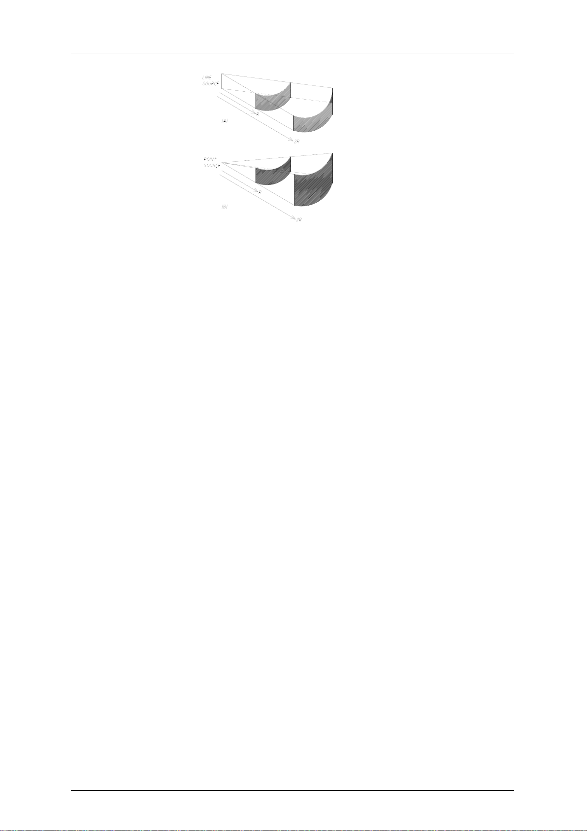
In the first zone (Fresnel), sound pressure loss is only 3 dB per doubling of distance,
whereas in the second zone (Fraunhofer) the loss is 6 dB. In long throw and high
SPL configurations it is very important to produce cylindrical waves.
NITID N208 Dec 2018
7Amate Audio
Fig. 7.Cylindrical wave (A) vs Spherical wave (B)
(A): -3 dB / doubling of distance
(B): -6 dB / doubling of distance
1.4 Features and presentation
N208
- Self-powered acoustic system
- XLR electronically balanced input & XLR parallel output
- AC PowerCon input and link
- Speakon NL4FX output
- 1000 W Class-D amplifier for low-mid range
- 500 W Class-D amplifier for high range
- 24-bit AD/DA converters, 48 kHz sampling rate
- Self amplifier diagnostics: output power, temperature, clipping
- DSP Controls (delay, volume, PEQ, presets and limiter)
- 2 x 8" neodymium woofers with 2.5” voice coil
- 2 x 1.7” voice coil diameter, 1” exit PEN diaphragm compression drivers
- High frequency planar waveguide
- 110º horizontal directivity
N208P
- Passive acoustic system
- Speakon NL4MPR input
- AC PowerCon input and link
- 2 x 8" neodymium woofers with 2.5” voice coil
- 2 x 1.7” voice coil diameter, 1” exit PEN diaphragm compression drivers
- High frequency planar waveguide
- 110º horizontal directivity
N18W
- Self-powered subwoofer
- XLR electronically balanced input & XLR parallel output
- AC PowerCon input and link
NITID N208 Dec 2018
8Amate Audio
- 2500 W Class-D amplifier
- 24-bit AD/DA converters, 48 kHz sampling rate
- Self amplifier diagnostics: output power, temperature, clipping
- DSP Controls (delay, volume, PEQ, presets, polarity and limiter)
- 18” woofer with 4” voice coil
N218W
- Self-powered subwoofer
- XLR electronically balanced input & XLR parallel output
- AC PowerCon input and link
- 2500 W Class-D amplifier
- 24-bit AD/DA converters, 48 kHz sampling rate
- Self amplifier diagnostics: output power, temperature, clipping
- DSP Controls (delay, volume, PEQ, presets, polarity and limiter)
- 2 x 18” woofers with 4” voice coil
1.5 Presets on N208
The N208 includes several manufacturer presets for different types of application.
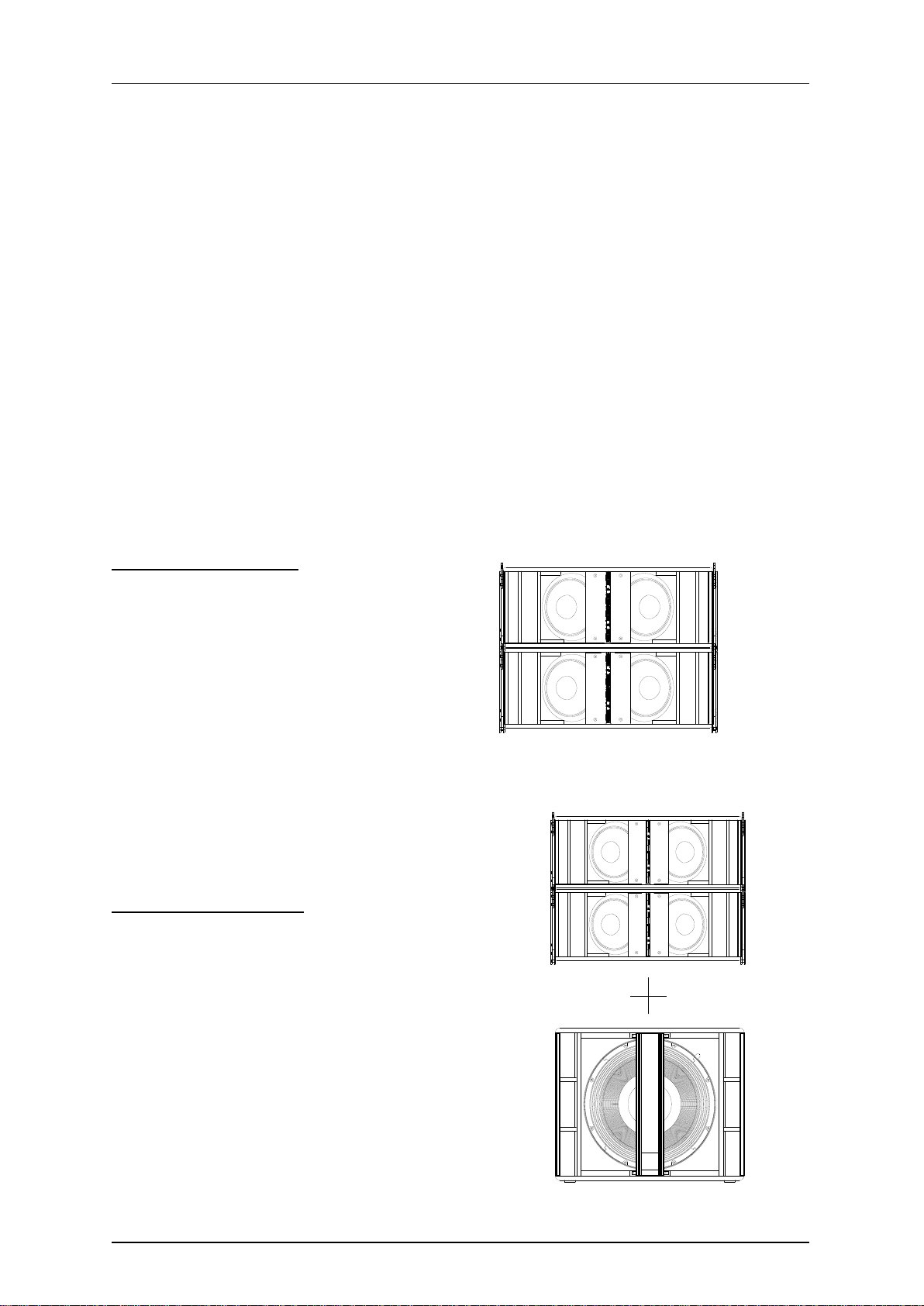
PRESET 1: 2BOX_FR
Two enclosures, full range
Fig. 8. Preset [2BOX_FR] configuration
PRESET 2: 2BOX_SW
Two enclosures with subwoofer
Fig. 9. Preset [2BOX_SW] configuration

NITID N208 Dec 2018
9Amate Audio
PRESET 3: 4BOX_FR
Four enclosures, full range
Fig. 10. Preset [4BOX_FR] configuration
PRESET 4: 4BOX_SW
Four enclosures with subwoofer
Fig. 11. Preset [4BOX_SW] configuration
PRESET 5: 8BOX_FR
Eight enclosures, full-range
Fig. 12. Preset [8BOX_FR] configuration
NITID N208 Dec 2018
10 Amate Audio
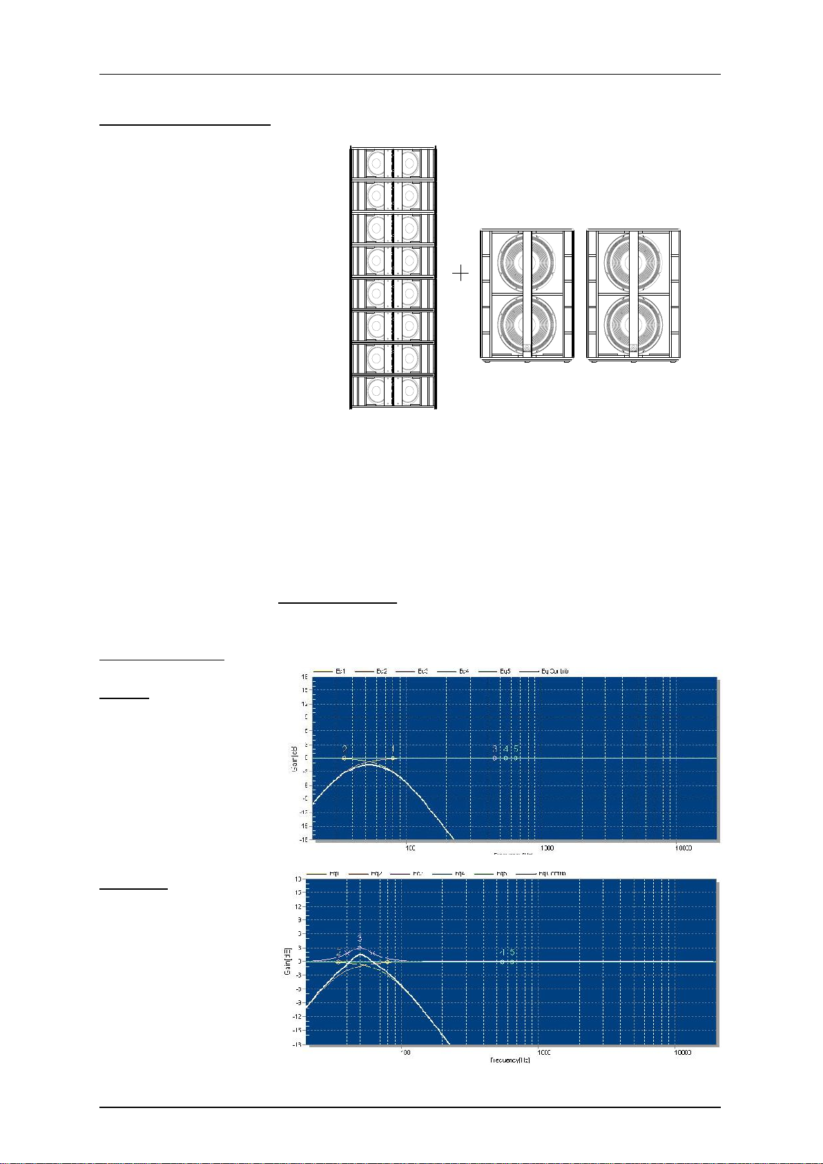
PRESET 6: 8BOX_SW
Eight enclosures with subwoofer
Fig. 13. Preset [8BOX_SW] configuration
1.6 Presets on N18W, N218W
The N18W and N218W include several manufacturer presets for different types of
applications.
ATTENTION: When the N18W or N218W are used in conjunction with the N208
NITID system in 2BOX_SW, 4BOX_SW or 8BOX_SW presets, the N18W and
N218W must operate in positive polarity.
When the N18W or N218W are used in conjunction with the N208 NITID system in
2BOX_FR, 4BOX_FR or 8BOX_FR presets, the N18W and N218W must operate in
negative polarity.
LPF80
80 Hz low pass filter
LPF80+3
80 Hz low pass filter
A) +3dB boost
at 50Hz (N18W)
B) +3dB boost
at 44Hz (N218W)
This manual suits for next models
1
Table of contents
Other Amate Audio Subwoofer manuals

Amate Audio
Amate Audio N12WP User manual

Amate Audio
Amate Audio XCELLENCE X218WFD User manual

Amate Audio
Amate Audio XCELLENCE XW218 User manual

Amate Audio
Amate Audio Nitid S12WP User manual

Amate Audio
Amate Audio XCELLENCE X212AF User manual

Amate Audio
Amate Audio Nitid S18W User manual

Amate Audio
Amate Audio NITID N18W User manual

Amate Audio
Amate Audio S18WP User manual

Amate Audio
Amate Audio KRW-118 User manual


