Albatron K7I741CX User manual

K7I741CX
Copyright
All rights are reserved. No part of this publication may be reproduced, transmitted, transcribed,
stored in a retrieval system or translated into any language or computer language, in any form or by
any means, electronic, mechanical, magnetic, optical, chemical, manual or otherwise, without the
prior written permission of the company. Brands and product names are trademarks or registered
trademarks of their respective companies.
The vendor makes no representations or warranties with respect to the contents herein and especially
disclaim any implied warranties of merchantability or fitness for any purpose. Further the vendor
reserves the right to revise this publication and to make changes to the contents herein without
obligation to notify any party beforehand. Duplication of this publication, in part or in whole, is not
allowed without first obtaining the vendor’s approval in writing.
Trademark
All the trademarks or brands in this document are registered by their respective owner.
Disclaimer
We make no warranty of any kind with regard to the content of this user’s manual. The content is
subject to change without notice and we will not be responsible for any mistakes found in this user’s
manual. All the brand and product names are trademarks of their respective companies.
FCC Compliance Statement
This equipment has been tested and found to comply with the limits of a Class B digital device,
pursuant to Part 15 of the FCC Rules. These limits are designed to provide reasonable protection
against harmful interference in a residential installation. This equipment generates, uses and can
radiate radio frequency energy and, if not installed and used in accordance with the instructions, may
cause harmful interference to radio communications. Operation of this equipment in a residential
area is likely to cause harmful interference in which case the user will be required to correct the
interference at his own expense. However, there is no guarantee that interference will not occur in a
particular installation.
CE Mark
The device is in accordance with 89/336 ECC-ENC Directive.

V
er: EG100

K7I741CX
SiS® 741CX & SiS®964 Chipset
Supports Socket 462
AMD®GeodeTM NX Processor
USER Manual
Dimensions (Mini-ATX form-factor):
z170 mm x 170 mm (W x L)
Operating System:
zWindows®XP/2000

Attention- Im
p
ortant Information
Follow the procedures below…
Troubleshooting Tips
Refer to other sections in this manual…
Things You Should Know
0The images and pictures in this manual are for reference only and may vary from the
product you received depending on specific hardware models, third party components
and software versions.
0This mainboard contains very delicate IC chips. Always use a grounded wrist strap
when working with the system.
0Do not touch any IC chip, lead, connector or other components.
0Always unplug the AC power when you install or remove any device on the mainboard
or when confuguring pins and switches.
Packing List
K7I741CX mainboard
HDD Cable
I/O Bracket
SATA Cable (Optional)
USB Cable (Optional)
K7I741CX Mainboard User Manual CD
K7I741CX Setup Driver CD
K7I741CX Mainboard Quick Installation Guide
Symbols
The following list explains the convention for symbols that will be used throughout this
manual:

Contents
CHAPTER 1. GETTING STARTED ............................................................1
INTRODUCTION ................................................................................................1
SPECIFICATION ................................................................................................2
CONFIGURATION..............................................................................................5
Layout of K7I741CX .........................................................................5
HARDWARE INSTALLATION .............................................................................6
CPU Processor Installation ................................................................6
Memory Installation: DIMM .............................................................7
Back Panel Configuration..................................................................9
Connectors .......................................................................................10
Headers & Jumpers..........................................................................12
Audio Configuration ........................................................................14
Slots..................................................................................................14
Power Supply Attachments ..............................................................15
CHAPTER 2. BIOS SETUP..........................................................................16
INTRODUCTION ..............................................................................................16
MAIN MENU ..................................................................................................17
CHAPTER 3: SOFTWARE SETUP............................................................19
SOFTWARE LIST.............................................................................................19
SOFTWARE INSTALLATION.............................................................................19
CHAPTER 4: TROUBLESHOOTING .......................................................22

K7I741CX Mainboard
1
Chapter 1. Getting Started
Introduction
Congratulations on the choosing the K7I741CX Mainboard. It is based on the SiS®741CX
Northbridge chipset and the SiS®964 Southbridge chipset with possessing integrated graphics feature.
The mainboard supports the AMD GeodeTM NX Processor with FSB (Front Side Bus) frequencies up
to 266 MHz.
The K7I741CX provides one DIMM (Dual In-Line Memory Modules) socket. The socket allows you
to install 184-pin, non-ECC & unbuffered DDR 333 (PC2700)/ DDR 200 (PC2100) SDRAM which
supports a total memory capacity of 1 GB.
The mainboard provides one IDE connector for two hard drives supporting Ultra ATA 133/ 100/ 66
IDE devices. In addition, the onboard comes with one PCI slot for use with a graphics card or
expansion cards which the PCI interface compatible.
Moreover, the K7I741CX provides one VGA connector (equal to D-Sub connector), one Printer port,
and one serial port for use. Several headers are also available on the mainboard for two USB 2.0/1.1
headers for front panel, one IrDA header and one COM header that can be connected additionally
with cables on the back panel of your case.
The onboard AC’ 97 Audio CODEC (ALC203) supports high quality performance 2-channel audio
play. Furthermore, there are maximal six USB2.0/ 1.1 ports which can be set up on this mainboard.
The K7I741CX also comes with an onboard 10/100 Mbps Ethernet LAN chip (RTL8201CL). There
is a LAN port on the back panel of your case that you can directly plug into an internet cable.
In addition, the mainboard comes with two SATA connectors (Optional) which the interface can
provide the transmit rate up to 1.5 Gbps.
All the information (including hardware installation and software installation) in this manual are for
reference only. The contents in this manual may be updated without notice. The company will not
assume any responsibility for any errors or mistakes within.

K7I741CX Mainboard
2
Specification
CPU:
zSupports Socket 462 (Socket A)
zSupports AMD®GeodeTM NX processors
zSupports FSB (Front Side Bus) Frequencies up to 266 MHz
Chipset:
zNorthbridge Chipset – SiS®764 CX
zSouthbridge Chipset – SiS®964
zI/O Controller – Winbond®W83627HG-AW
zAC’ 97 Aduio Codec – Realtek®ALC203
zLAN PHY – Realtek® RTL8201CL LAN PHY
Memory:
zOne DIMM socket
zSupports a total memory capacity of 1 GB
zSupports to use the 184-pin, unbuffered & non-ECC DDR333 (PC2700)/ DDR266
(PC2100) SDRAM
AC’97 Sound CODEC Onboard:
zHigh performance CODEC with high S/N ratio (>100 db)
zCompliant with AC’ 97 2.3 specification
zSupport 2-channel playback capability
zSupport 3D stereo enhancement
Slots:
zOne 32-bit slot for PCI interface for expansion cards
zSupports one-way bandwidth up to 133 MB/s per channel
Onboard IDE Connector:
zOne IDE connector that supports up to two IDE devices
zSupports Ultra ATA 133/ 100/ 66/ 33
zSupports high capacity hard disk drives

K7I741CX Mainboard
3
Serial ATA Connector (Optional):
zTwo SATA connectors that support up to two SATA hard disk drives
zSupports SATA 1.0 specification which provides 1.5 Gb/s transmit rate
zSupports RAID 0/ 1 mode
I/O facility Connectors:
zOne multi-mode Parallel Port is capable of supporting the following specifications:
1. Standard & Bi-direction Parallel Port
2. Enhanced Parallel Port (EPP)
3. Extended Capabilities Port (ECP)
zSupport one serial port and one VGA port
zSupports one PS/2 mouse port and one PS/2 keyboard port
zSupports one IrDA header, two USB headers, and one COM header compatible with
external devices connected
Universal Serial Bus:
zTwo onboard USB 2.0/ 1.1 ports
zTwo front USB 2.0/ 1.1 headers come with this mainboard supporting four additional
USB 2.0/ 1.1 ports to be set
zSupports a maximum of six USB 2.0/ 1.1 ports for compliant devices
Onboard LAN Chip:
zSupports 10/100 Mbps Ethernet LAN
zSupports Auto-negotiation (NWAY) function of full/half duplex operation for both 10
Mbps and 100 Mbps
BIOS:
zPhoenix-Award™ BIOS
zSupports APM 1.2
zSupports ACPI 2.0 power management
Green Function:
zSupports Phoenix-Award™ BIOS power management function
zSupports system-wake-from-power-saving-mode by keyboard or mouse touching

K7I741CX Mainboard
4
Shadow RAM:
zIntegrated memory controller provides shadow RAM functionality and supports ROM
BIOS
Flash Memory:
zSupports flash memory functionality
zSupports ESCD functionality
Hardware Monitor Function:
zMonitors CPU/ Chassis Fan Speed
zMonitors CPU and system temperatures
zMonitors system voltages
Watch Dog Timer:
zThis function is used for detecting the system hangs during the POST stage due to
conflicts resulting from changing the system BIOS settings. Once the problem is detected,
the system will reset the configurations and reboot the system within five seconds.

K7I741CX Mainboard
5
Configuration
Layout of K7I741CX

K7I741CX Mainboard
6
Hardware Installation
This section will assist you in quickly installing your system hardware. Wear a wrist ground strap
before handling components. Electrostatic discharge may damage your system components.
CPU Processor Installation
This mainboard supports AMD®GeodeTM NX processors using a Socket A (Socket 462 Pin package).
Before building your system, we suggest you visit the AMD website and review the processor
installation procedures. http://www.amd.com
CPU Socket A Configuration Steps:
1. Locate the CPU socket on your mainboard and nudge the lever away from the socket. Then lift
the lever to a 90-degree angle.
2. On the socket, locate the corner that has the pin-1 receptor. This corner will have a cut-corner
on the rectangular shaped pattern of pin holes on the socket.
Match the corner on the CPU with the pin-1 receptor on the socket and lower the CPU onto the
socket. The bottom of the CPU should be flush with the face of the socket.
3. Lower the lever until it snaps back into position. This will lock down the CPU.
4. Smear thermal grease on top of the CPU. Lower the CPU fan onto the CPU and use the clasps
on the fan to attach it to the socket. Finally, extend the power cable from the fan and insert it
onto the CPUFAN adapter.
Pin-1
Receptor Gold Triangle
This manual suits for next models
1
Table of contents
Other Albatron Computer Hardware manuals
Popular Computer Hardware manuals by other brands

EMC2
EMC2 VNX Series Hardware Information Guide

Panasonic
Panasonic DV0PM20105 Operation manual

Mitsubishi Electric
Mitsubishi Electric Q81BD-J61BT11 user manual

Gigabyte
Gigabyte B660M DS3H AX DDR4 user manual

Raidon
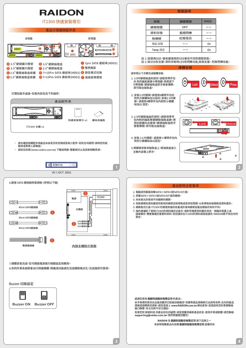
Raidon iT2300 Quick installation guide

National Instruments
National Instruments PXI-8186 user manual