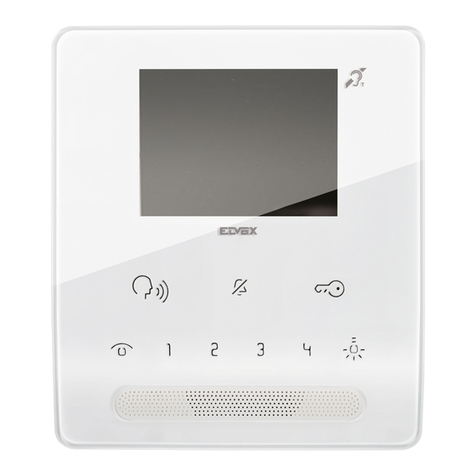
Akuvox R20K User manual

Torx Wrench x 1
Rope x 1
R20K x 1
ST4x20 screw x 4
Screw fixing seat x 4
M2.5x6 screw x 6
Back cover x 1
Mainframe Accessories (Please find in device box) :
Rubber Plug x 3 (S,M,L)
wall-mounng screws
Cable locking plate x 1
Before you begin using the device, please check the version you got and ensure that the following items
are included in the shipped box:
Adjustable Angle Wall-mounng Accessories :
R20K BACK VIEW ADJUSTABLE ANGLE BRACKET LEFT SIDE VIEW
ADJUSTABLE ANGLE BRACKET BOTTOM VIEW
85.0mm
185.0mm
R20K BOTTOM VIEW
24.0mm
Wall-mounting template x 1
wall-mounting
screws holes
M3x6 Torx screw
184.0mm
WAL L
M3x6 Torx screw
1.45
Adjustable angle bracket x 1 M4x30 screw x 2
M3x6 Torx screw x 2
Adjustable Angle Wall-mounng Installaon
R20K

1.45
1. Without embedded juncon box in the wall
Insert four screw fixing
seats into the holes.
Step1: Adjustable angle bracket Installaon
2
According to the baseline on
the mounting template, stick
the mounting template on the
wall or other surface.
Use a drill with 5mm diameter
bit to make four holes in the
“Hole 3” positions.
Select the suitable holes
on the adjustable angle
bracket to make sure the
cables can route through it.
Fixing the bracket with four
ST4x20 screws.
WALL
WALL
Installed on the left side of the door Installed on the right side of the door
2. With embedded one-gang juncon(2x3 inches) in the wall.
Select the suitable holes on
the adjustable angle bracket
to make sure the cables can
route through it.
Fixing the adjustable angle
bracket and junction box with
two M4x30 screws.
WALL
WALL
Installed on the left side of the door Installed on the right side of the door
1.45
GRO UND

3
Step3:Device Installaon
Insert the wall-mounting screws on the device into
the corresponding holes on the adjustable angle
bracket, and then pull up to slide the wall-mounting
screws into the groove. Then use the Allen wrench
to tighten the device with two M3x6 screws.
Step2:Back Cover Installaon
Make cables go through the back
cover, connecting to the
corresponding interfaces of the main
board. Select a suitable size rubber
plug to push all the cables into the
back cover. Fix cable locking plate to
the back cover with two M2.5x6
screws.
Note: In the case of one network cable
or less than 6 signal cables, use
S-size rubber plugs. In the case of 7
to 10 signal cables, use M-size rubber
plugs. When there are more than 11
signal cables Please use L-size wiring
rubber plug.
Fasten the back cover
with four M2.5x6 screws.
Insert the wall-mounting screws on the device into the
corresponding holes on the adjustable angle bracket,
and then press down to slide the wall-mounting screws
into the groove. Then use the Allen wrench to tighten
the device with two M3x6 screws.
Installed on the left side of the door. Installed on the right side of the door.
Adjustable Angle Wall-mounng Installaon
R20K

4
Completed.
Adjust to an appropriate angle(30 ° ~ 60 °) and
use the Torx wrench to tighten one M3x6 Torx
screw on the upper and lower ends of the
adjustable angle bracket.
0°~30°
WALL
AKUVOX (XIAMEN) NETWORKS CO., LTD.
ADD: 10/F, NO.56 GUANRI ROAD, SOFTWARE PARK II, XIAMEN 361009, CHINA
www.akuvox.com
Notice Information
Akuvox R20K firmware contains third-party open source software under the terms of the GNU General Public
License(GPL). Akuvox is committed to meeting the requirements of the GNU General Public License (GPL) and will
make all required source code available.
The source code of software under the terms of GNU GPL can be downloaded online: http://www.akuvox.com/gpl.
Information contained in this document is believed to be accurate and reliable at the time of printing. This document is
subject to change without notice, any update to this document can be viewed on Akuvox’ s website:
http://www.akuvox.com © Copyright 2020 Akuvox Ltd. All rights reserved.
Adjustable Angle Wall-mounng Installaon
R20K
Other manuals for R20K
2
Other Akuvox Intercom System manuals

Akuvox
Akuvox C313 Series User manual

Akuvox
Akuvox E18C Service manual

Akuvox
Akuvox IT88 Series Manual

Akuvox
Akuvox R27V Manual

Akuvox
Akuvox E16 Series Service manual

Akuvox
Akuvox R29 Series Service manual

Akuvox
Akuvox C315 Manual

Akuvox
Akuvox R20A User manual

Akuvox
Akuvox A05 Series Service manual

Akuvox
Akuvox Smart Intercom R29 Series Manual