
AJ SSLFHFD-FFU User manual

STAINLESS STEEL
SSLFHFD-FFU
CRITI-CLEAN ULTRA FAN FILTER UNIT
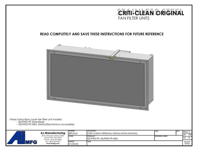
-These instructions cover fan filter unit models:
- SSLFHFD-FFU (Standard, top side access)
- SSLFHFD-FFU-MEA (Motor/Electronics Accessible, room side access)
READ COMPLETELY AND SAVE THESE INSTRUCTIONS FOR FUTURE REFERENCE
DRAWN
MATERIAL
CHKD
APRVD
FINISH
SIZE
ENGINEER
CONTRACTOR
TAG QTY
BRS
REV #
E
SHT
1 30
/
SCL
DO NOT
SCALE
1:10
JOB NAME
A copy of these installation instructions can be obtained at this webpage:
WWW.AJMFG.COM
DRAWING NAME
DRAWN
MATERIAL
CHKD
APRVD
FINISH
SIZE
ENGINEER
CONTRACTOR
TAG QTY
BRS
REV #
E
SHT
1 30
/
SCL
DO NOT
SCALE
1:10
JOB NAME

STAINLESS STEEL
SSLFHFD-FFU
CRITI-CLEAN ULTRA FAN FILTER UNIT
Critical operation conditions of the Fan Filter Unit
x
DO NOT TOUCH the HEPA filter media. Damage to filter media may void the filter warranty. The screen is to protect against accidental
contact with the filter. Never place objects on the filter. Always transport or lift the filter by its frame.
x
Prior to powering the unit, verify that it is wired to the correct power supply. The rating plate label located on the electrical box
shows the electrical data.
x
For replacement parts refer to the model number and serial number on the rating plate label located on the electrical box.
Replacement Part numbers
FFU-RP11 - 48 x 24 x 3.5" High-Flow HEPA filter
FFU-RP12 - 36 x 24 x 3.5" High FlowHEPA filter
FFU-RP13- 24 x 24 x 3.5" High Flow HEPA filter
FFU-RP14 - 14 x 14 x 3/8 Expanded aluminum pre-filter (2-ply)
FFU-RP21 - Variable speed motorized impellor (120 VAC)
FFU-RP22 -Variable speed motorized impellor (208, 240, 277 VAC)
FFU-RP31 - Main control board
FFU-RP32 - Airflow measure and display system
FFU-RP33 - Face control/display board (board only)
FFU-RP34 - 120 -- 24 VAC transformer
FFU-RP35 - 208/240 -- 24 VAC transformer
FFU-RP36 - 277 -- 24 VAC transformer
FFU-RP37 - Network power control circuit board
FFU-RP38 - PAO challenge system
FFU-RP39 - Safety shut-off switch
WHEN ORDERING REPLACEMENT PARTS, PLEASE INCLUDE UNIT MODEL & SERIAL NUMBER AND PO # IF AVAILABLE.
FPH-RP40 - Resetable fuse (8A up to 240 VAC)
FPH-RP41 - Fuse holder with fuse (5A @ 277 VAC)
FPH-RP42 - Cartridge fuse (5A @ 277 VAC)
INSTALL AND OPERATION
DRAWING NAME
DRAWN
MATERIAL
CHKD
APRVD
FINISH
SIZE
ENGINEER
CONTRACTOR
TAG QTY
BRS
REV #
E
SHT
2 30
/
SCL
DO NOT
SCALE
1:10
JOB NAME

STAINLESS STEEL
SSLFHFD-FFU
CRITI-CLEAN ULTRA FAN FILTER UNIT
READ COMPLETELY AND SAVE THESE INSTRUCTIONS
WARNING - TO REDUCE THE RISK OF FIRE, ELECTRIC SHOCK, OR INJURY TO PERSONS,
ALLOW ONLY QUALIFIED TECHNICIANS TO INSTALL AND SERVICE THE UNIT. ALL
PERSONS SHOULD OBSERVE THE FOLLOWING:
a) Use this unit only in a manner intended by the manufacturer. If you have questions, contact the manufacturer.
b) Before servicing or cleaning unit, switch power off at the servicepanel and lock-out the service in accordance with OSHA (LOTO)
practices and procedures to prevent power from being accidentally switched on avoiding accidental electric shock and injury. When
the service disconnecting means cannot be locked,securely fasten a prominent warning device, such as a tag, to the service panel.
x
Installation work and electrical wiring must be completed by qualified personnel in accordance with all applicable codes and
standards, to include fire-rated constructions.
x
When cutting or drilling into walls and ceilings, be careful not to damage electrical wiring and other hidden utilities.
x
If this unit is to be installed within close proximity to water, mark the unit in accordance with applicable codes and standards.
x
This unit is to be used only as intended by the manufacturer. If you have any questions regarding the use, installation, or
operation of this unit, contact the manufacturer:
AJ Manufacturing Co., Inc.
8701 Elmwood Avenue; Suite 400
Kansas City, MO 64132
Tel: 816-231-5522
INSTALL AND OPERATION
DRAWING NAME
DRAWN
MATERIAL
CHKD
APRVD
FINISH
SIZE
ENGINEER
CONTRACTOR
TAG QTY
BRS
REV #
E
SHT
3 30
/
SCL
DO NOT
SCALE
1:10
JOB NAME

STAINLESS STEEL
SSLFHFD-FFU
CRITI-CLEAN ULTRA FAN FILTER UNIT
INSTALLATION CHECKLIST
This is to provide a general overview of what steps should be taken to achieve a successful installation of the fan
filter unit. These steps should be performed in the order listed. For more detail see applicable section in this instruction
manual. Read the entire manual before begining installation.
□
Prepare the installation site with appropriate power, data cabling, support structure, and openings as needed.
□
Unbox and inspect the fan filter unit.
□
Install the fan unit into the ceiling. Support its weight from structure above.
□
Connect ductwork to fan unit (if applicable).
□
Seal the fan filter unit to the ceiling using gasketing and caulking.
□
If the unit is to be ducted, set upstream air device to produce 0.0" W.C. static pressure at the fan unit inlet.
Use dampers if necessary if installing mutiple fan units on the same duct line.
□
Connect main power wiring.
□
Connect control wiring (if applicable).
□
Run the unit and/or upstream air device to flush out construction debris.
□
Install the pre-filter (if applicable).
□
Install the HEPA/ULPA filter.
□
Turn unit on and adjust airflow to design CFM.
□
Turn on the upstream airflow device.
□
Leak test the fan unit and filter per local codes and building procedures.
□
Install the perforated face screen.
□
Verify airlow with a flow hood.
INSTALL AND OPERATION
DRAWING NAME
DRAWN
MATERIAL
CHKD
APRVD
FINISH
SIZE
ENGINEER
CONTRACTOR
TAG QTY
BRS
REV #
E
SHT
4 30
/
SCL
DO NOT
SCALE
1:10
JOB NAME

STAINLESS STEEL
SSLFHFD-FFU
CRITI-CLEAN ULTRA FAN FILTER UNIT
Main Power Switch
Line Power
Knock Out
Main Control Board
Installation
The terminal unit is fully assembled from the factory with the exception
of the HEPA filter and duct kit (if applicable). Filter is shipped in a separate box.
Step 1 -- Carefully remove the unit from the shipping carton and inspect for
damage that may have occurred during shipping. If shipping damage is found,
do not install. Call the supplier to report damage.
Step 2 -- Wipe down unit to remove shipping dust and debris.
Step 3 -- Raise unit into position and secure using the hanger tabs. Alternately it can be secured
a framed opening through the frame if care is taken not to damage the knife edge and
all penetrations are sealed. Any gasket should be a closed-cell material approved for the
environmental conditions. Sealant used to seal the unit to the ceiling should be approved
for the application and conditions.
Step 4 -- A qualified technician should connect the unit to the appropriate
power supply per applicable codes and standards. Refer to the wiring
diagrams included in these instructions. -FFU units: the electrical
box will be accessible from the plenum side. -FFU-MEA units: the electrical
box will be accessible from the roomside.
SSLFHFD-FFU-120 --- 120 VAC SUPPLY,
2.8 FLA
SSLFHFD-FFU-208 --- 208 VAC SUPPLY,
2.6
FLA
SSLFHFD-FFU-240 --- 240 VAC SUPPLY, 2.3 FLA
SSLFHFD-FFU-277 --- 277 VAC SUPPLY, 1.9 FLA
Step 5 -- Blow out / clean entire duct system leading to unit to remove construction
debris. This is especially important for motor accessible units as they do not have a
pre-filter. Wash pre-filter if applicable per “Cleaning the Fan Filter Unit Pre-filter” on page 7.
Step 6 -- Install the HEPA filter per the “Removal and Replacement of the HEPA Filter
with Gel Seal” section.
NOTE: FOR DUCTED INSTALLATIONS, IT IS RECOMMENDED
THAT PRIMARY AIR BALANCING TO ACHIEVE 0.0"WC INLET
STATIC PRESSURE BE DONE BEFORE FAN FILTER UNIT IS
CONNECTED TO DUCT SYTEM.
NOTE:
An additional disconnect should be added
by others per applicable codes and regulations.
INSTALL AND OPERATION
DRAWING NAME
DRAWN
MATERIAL
CHKD
APRVD
FINISH
SIZE
ENGINEER
CONTRACTOR
TAG QTY
BRS
REV #
E
SHT
5 30
/
SCL
DO NOT
SCALE
1:10
JOB NAME

STAINLESS STEEL
SSLFHFD-FFU
CRITI-CLEAN ULTRA FAN FILTER UNIT
A NOTE ABOUT VAV BOXES AND DUCTED APPLICATIONS
In applications where the fan filter unit will be installed downstream of variable airflow devices such as
VAV boxes, air valves, or variable air handlers, proper care in unit set-up needs to be taken.
In these applications the unit should not be programed to run as constant airflow when ordered with the Airflow Sensor.
Two variable controllers trying to reach their respective set point will continuously adjust. This will cause issues such as
surging, starving, and eventual shut down of the fan filter unit. In these applications the unit should be placed into
"open-loop" control by turning off the S1-1dip switch (see pict below). This will no longer keep constant airflow
automatically. It will also remove the dirty filter ramp-up feature and the HEPA-lert dirty filter indicator (if applicable) will
be set as a static timer of 4400 hours (about 6 months). The set point will now be a percentage of motor speed instead
of CFM but it will still display CFM during normal operation. The unit in this setting is still preferable to a PSC system due to
the energy efficiency of an ECM versus a PSC motor and all control options are still applicable.
DUCTED APPLICATIONS
If ordered with the Airflow Sensor option the condition immediately before the inlet can impact the CFM reading. Use
the "C" up and down arrows on the face control to calibrate the airflow sensor to match the balancer's flow hood to
insure accurate airflow control. This calibration is best done as near to the operating point as possible. Recalibration may
be required if the setpoint changes more than 25%. In extreme cases the inlet conditions may not be able to be
compensated for using the caliberation adjustment. In these cases CFM controlled opperation may have to be forfit
and the unit run in open-loop mode.
While the fan filter unit can handle some positive or negative static pressure, optimal
performance and reliability will be achieved with an inlet static pressure of 0.0" WC or slightly negative.
To reach an accurate 0.0"WC inlet static, it is recommended that the primary air balancing of the duct system
be done before installing the fan filter unit. When the duct is at optimal static, install the unit per these
instructions and adjust the airflow to the design setting. Verify the airflow with an airflow hood.
S1-1
INSTALL AND OPERATION
DRAWING NAME
DRAWN
MATERIAL
CHKD
APRVD
FINISH
SIZE
ENGINEER
CONTRACTOR
TAG QTY
BRS
REV #
E
SHT
6 30
/
SCL
DO NOT
SCALE
1:10
JOB NAME

STAINLESS STEEL
SSLFHFD-FFU
CRITI-CLEAN ULTRA FAN FILTER UNIT
Pre-filter
Access
Panel
Duct Kit
Pre-filter
Pre-filter
Retainer
Clips
Cleaning the Fan Filter Unit Pre-filter
(when applicable)
WARNING!
Disconnect the unit from the electrical power source before attempting to service the unit.
Note: For maximum performance, wash pre-filter every three to six months at a minimum.
Step 1 -- Turn the unit off with the toggle switch located on the unit.
Step 2 -- Disconnect the unit at the power source or at the service panel in accordance with OSHA
(LOTO) practices and procedures.
Step 3 -- For ducted applications, use a driver to remove the screws holding the access panel. Slide the pre-filter
out of the duct kit. If the unit is non-ducted, remove the pre-filter from the retainer clips
For plenum applications, slide the filter diagonally against two of the retaining clips. This should free
the opposite sides. Lift the free corner above the clips and pull the filter out of the remaining two clips.
Step 4 -- Wash the filter with hot water and a mild detergent and rinse thoroughly. Do not use a caustic solution
to clean the filter. Blow dry or let air dry.
Filter should be completely dry before reinstalling into unit.
Step 5 -- Filter installation is the reverse of the removal procedure.
INSTALL AND OPERATION
DRAWING NAME
DRAWN
MATERIAL
CHKD
APRVD
FINISH
SIZE
ENGINEER
CONTRACTOR
TAG QTY
BRS
REV #
E
SHT
7 30
/
SCL
DO NOT
SCALE
1:12
JOB NAME

STAINLESS STEEL
SSLFHFD-FFU
CRITI-CLEAN ULTRA FAN FILTER UNIT
FACE FRAME
HEPA/ULPA Filter
Removal and Replacement of the HEPA Filter with Gel Seal
WARNING!
Disconnect the unit from the electrical power source before attempting to service the unit.
WARNING!
The HEPA filter may be protected by an expanded metal screen. The screen prevents accidental contact with the filter media.
It is not meant to allow handling of the filter by the media. Handle the filter ONLY by the frame.
NOTE: The manufacturer recommends two people to remove and install the HEPA filter in the unit.
Step 1 -- Using a flat screwdriver, release the face frame by rotating the four (4) fasteners a 1/4-turn counter clock-wise.
Unhook the safety cables from the filter clips. Set the frame aside.
Step 2 -- Turn the unit off with the switch located on the face of the unit (round, black button).
Step 3 -- Disconnect the unit at the power source or at the service panel in accordance with OSHA (LOTO)
practices and procedures.
Step 4 -- USE TWO PEOPLE TO SUPPORT THE FILTER and rotate the swingarm filter clips off of the filter until
clip is clear of the filter.
Step 4 ALT (if stud style filter clips) -- Using a 7/16” nut-driver, evenly loosen the nuts holding the filter retaining
clips by working your way around the unit loosening the nuts a little at a time. To make installing the new
filter easier, loosen the nuts until flush with the end of the threaded stud. USE TWO PEOPLE TO SUPPORT
THE FILTER and rotate the filter clips toward the offset hole until clip is clear of the filter.
Step 5 -- Allow gravity to pull the filter away from the unit. If installing a new filter discard the filter in an
appropriate manor.
Step 6 -- Unpack the new filter and inspect for shipping damage. If damage is found, do not install in unit; call the
vendor for replacement arrangements.
Step 7 -- Using two people, raise the filter into place in between the filter guides (or threaded posts if stud style) assuring the seal edge is
approximately in the center of the gel channel.
Step 8 -- While supporting the filter by its frame, rotate the filter clips so that the clips are supporting the frame
and are at 90° to the frame. (ALT--Evenly tighten the nuts by working your way around the unit tightening the nuts
a little at a time. Stop tightening when the aluminum filter frame contacts the stainless steel housing frame of the unit.
DO NOT OVER TIGHTEN
). Wait at least 30 minutes before performing any challenge testing to allow the
gel to fully adhere to the unit.
Step 9 -- Inspect all gaskets and seals for integrity. Reconnect power and turn unit power on.
Step 10 -- Raise the face frame back into place, reattach the safety chains, and secure 1/4-turn fasteners.
INSTALL AND OPERATION
DRAWING NAME
DRAWN
MATERIAL
CHKD
APRVD
FINISH
SIZE
ENGINEER
CONTRACTOR
TAG QTY
BRS
REV #
E
SHT
8 30
/
SCL
DO NOT
SCALE
1:12
JOB NAME

STAINLESS STEEL
SSLFHFD-FFU
CRITI-CLEAN ULTRA FAN FILTER UNIT
Motor Mount
Screws (x4)
Motorized
Impeller
Fan Inlet Box
Screws (x8)
Removal and Installation of the Variable Speed Motor (SSLFHFD-FFU)
WARNING!
Disconnect the unit from the electrical power source before attempting to service the unit.
Step 1 -- Turn the unit off with the switch located on the face of the unit.
Step 2 -- Disconnect the unit at the power source or at the service panel in accordance with
OSHA (LOTO) practices and procedures.
Step 3 -- Remove the HEPA filter and set aside. See sections 2 and 3 for instructions.
Step 4 -- Disconnect the 3-pin power plug and the 4-pin data plug from the electrical box.
Step 5 -- Use a 4 mm hex driver to remove the four (4) screws holding the motor to the
motor bracket inside the unit.
Step 6 -- Remove the duct from the unit, if applicable.
Step 7 -- Use a 5/16” driver to remove the eight (8) screws holding the Fan Inlet Box. Remove
Fan Inlet Box and set aside.
Step 8 -- Lift the motorized impeller out of the unit.
Step 9-- Reverse above steps to reassemble the motor/fan/ring assembly into the unit.
INSTALL AND OPERATION
DRAWING NAME
DRAWN
MATERIAL
CHKD
APRVD
FINISH
SIZE
ENGINEER
CONTRACTOR
TAG QTY
BRS
REV #
E
SHT
9 30
/
SCL
DO NOT
SCALE
1:10
JOB NAME

STAINLESS STEEL
SSLFHFD-FFU
CRITI-CLEAN ULTRA FAN FILTER UNIT
Motor Mount
Bracket Screws (x8)
Motor Mount
Screws (x4)
Motor Mount
Bracket (x4)
Motorized
Impeller
Airflow Guides
for PAO option
Removal and Installation of the Variable Speed Motor
(SSLFHFD-FFU-MEA)
WARNING!
Disconnect the unit from the electrical power source before attempting to service the unit.
Step 1 -- Using a flat screwdriver, release the face frame by rotating the four (4) fasteners a 1/4-turn
counter clock-wise. Unhook the safety cables from the filter clips. Set the frame aside.
Step 2 -- Turn the unit off with the switch located on the frame of the unit.
Step 3 -- Disconnect the unit at the power source or at the service panel in accordance with OSHA (LOTO)
practices and procedures.
Step 4 -- Remove the HEPA filter and set aside. See sections 2 and 3 for instructions.
Step 5 -- Disconnect the 3-pin power plug and the 4-pin data plug from the electrical box.
Step 6 -- Use a 7/16" driver to remove the eight (8) motor mount bracket screws.
Step 7 -- Lower the motor/bracket assembly out of the unit.
Step 8 -- Use a 4 mm hex driver to remove the four (4) screws holding the motor brackets to the motor.
Step 9 -- Reverse above steps to reassemble the motor/fan/ring assembly into the unit.
INSTALL AND OPERATION
DRAWING NAME
DRAWN
MATERIAL
CHKD
APRVD
FINISH
SIZE
ENGINEER
CONTRACTOR
TAG QTY
BRS
REV #
E
SHT
10 30/
SCL
DO NOT
SCALE
1:10
JOB NAME
This manual suits for next models
2
Table of contents
Other AJ Water Filtration System manuals

Popular Water Filtration System manuals by other brands

Wisy
Wisy LineAir 100 Installation and operating instructions

Schaffner
Schaffner Ecosine FN3446 Series User and installation manual

Pentair
Pentair FLECK 4600 SXT Installer manual

H2O International
H2O International H20-500 product manual

Renkforce
Renkforce 2306241 operating instructions

Neo-Pure
Neo-Pure TL3-A502 manual


