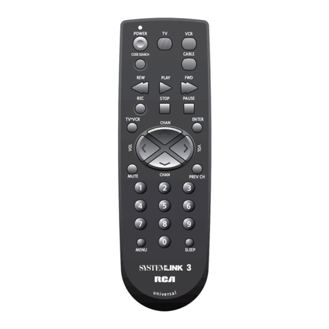
Air Star KJR-120G1/TFBG-E Installation instructions

MODEL: KJR-120G1/TFBG-E(5V)
KJR-120G2/TFBG-E(12V)
WIRED REMOTE CONTROLLERE
Installation and
Owner’s Manual
IMPORTANT NOTE:
Read this manual carefully before
installing or operating your wired
remote controller. Make sure to save
this manual for future reference.


● This manual gives detailed description of the precautions
that should be brought to your attention during operation.
● In order to ensure correct service of the wired controller
please read this manual carefully before using the unit.
● For convenience of future reference, keep this manual
after reading it.

CONTENTS
1. SAFETY PRECAUTION.............................................................................. 1
2. INSTALLATION ACCESSORY.................................................................... 2
3. INSTALLATION METHOD...........................................................................4
4. SPECIFICATION........................................................................................10
5. FEATURE AND FUNCTION OF THE WIRED CONTROLLER.................11
6. NAME ON THE LCD OF THE WIRE CONTROLLER.............................12
7. NAME OF BUTTON ON THE WIRE CONTROLLER................................13
8. PREPARATORY OPERATION..................................................................14
9. OPERATION..............................................................................................15
10. TIMER FUNCTIONS................................................................................21
11. WEEKLY TIMER......................................................................................24
12. FAULT ALARM HANDING.......................................................................31
13.TECHNICAL INDICATION AND REQUIREMENT ...................................31

1
Read the safety precautions carefully before installing the unit.
Stated below are important safety issues that must be obeyed.
Means improper handling may lead to personal death or severe injury.
Means improper handling may lead to personal injury or property loss.
WARNING
CAUTION
Please entrust the distributor or professionals to install the unit.
Installation by other persons may lead to imperfect installation, electric shock or fire.
Adhere to this installation manual.
Imporper installation may lead to electric shock or fire.
Reinstallation must be performed by professionals.
WARNING
Do not install the unit in a place vulnerable to leakage of flammable gases.Once
flammable gases are leaked and left around the wire controller, fire may occure.
Do not operate with wet hands or let water enter the wire controller. Otherwise,
electric shock may occur.
The wiring should adapt to the wire controller current. Otherwise, electric leakage or
heating may occur and result in fire.
The specified cables shall be applied in the wiring. No external force may be applied
to the terminal. Otherwise, wire cut and heating may occur and result in fire.
NOTE
Do not uninstall the unit randomly.
Random uninstalling may lead to abnormal operation, heating or fire of the air condition.
1
2
3
4
1. SAFETY PRECAUTION

2
2. INSTALLATION ACCESSORY
Don’t install at the place where cover with heavy oil, vapor or sulfureted gas,
otherwise, this product would be deformed that would lead to system malfunction.
Select the installation location
Preparation before installation
1. Please confirm that all the following parts you have been supply.
2. Prepare the following assemblies on the site.
1
2
3
4
5
3
2
M4X20 (For Mounting on the Wall)
M4X25 (For Mounting on switch box)
1
2
1
6
7
8
No. Name Qty. Remarks
Wire controller
Installation and owner’s manual
For Mounting on the Wall
Switch box
Wiring Tube(Insulating
Sleeve and Tightening
Screw)
Qty.(embeded
into wall)
Plastic screw bars
Screws
Wall plugs
For fixing on switch box
Optional
No. Name Remarks
Specification
(only for reference)
Screws
1
Battery
The connective wires group

2. INSTALLATION ACCESSORY
Precaution of install the wire controller
1. This manual provides the installation method of wire controller. Please refer to the
wiring diagram of this installation manual to wire the wire controller with indoor unit.
2. The wire controller working in low voltage loop circuit. Forbid to directly contact the
cable of 220Vcommercial electricity or of 380V high voltage, and don’t wire this kind
of wire in the said loop; wiring clearance between configured tubes should at the
range of 300~500mm or above.
3. The Shielded wire of the wire controller must be grounded reliable.
4. Upon finish the wire controller connection, do not employed tramegger to detect the
insulation.

4
3. INSTALLATION METHOD
Fig 3-1
1.Wired remote controller structure size figure
123mm
(4.8”)
120mm
(4.7”) 18.5mm
(0.7”)
83.5mm
(3.3”)
46mm
(1.8”)
62mm
(2.4”)
Fig 3-2
2.Wiring Principle Sketch:
red
black
yellow
brown
red
black
yellow
brown
Insert of the
mainboard CN40
Wire controller Indoor unit mainboard
4-Core Shield Cable, the length
is decided by installation
-----------------------------------
-----------------------------------
-----------------------------------
-----------------------------------

5
3. INSTALLATION METHOD
Fig 3-4
4.Remove the upper part of wire controller
Insert a slot screwdriver into the slots in the lower
part of the wire controller (2 places), and remove
the upper part of the wire controller. (Fig.3-4)
Slots
NOTICE
The PCB is mounted in the upper part of the wire
controller. Be careful not to damage the board
with the slot screwdriver.
Connect the female joint of wires group from the mainboard with the male joint of
connective wires group. (See Fig.3-3)
Please connect the other side of connective wires group with the male joint of
wires group leads from wire controller. (See Fig.3-3)
Fig 3-3
Mainboard
4-core shielding wire
3.Wiring figure
The connective wires group
CN40

6
3. INSTALLATION METHOD
Fig 3-5
Fig 3-6
Switch box
Back plate
For exposed mounting, fasten the back plate on the wall with the 3 screws (M4×20)
and plugs. (Fig.3-5)
For flush-mounting, fasten the back plate on the switch box with 2 screws (M4×25) and
fasten it on the wall with 1 screw (M4×20). (Fig.3-6)
5. Fasten the back plate of the wire controller
Back plate
Screws (M4×20)
Screw (M4×20)
Screws (M4×25)
NOTICE
Put on a flat surface. Be careful not to distort the back plate of the wire controller
by overtightening the mounting screws.
This manual suits for next models
1
Table of contents