
AGA Dual Control Series User manual

11/15 EINS 516845
PLEASE READ THESE INSTRUCTIONS BEFORE COMMENCING SITE SURVEY
OR INSTALLING THIS APPLIANCE.
RE E BER: when replacing a part on this appliance, use only spare parts that
you can be assured conform to the safety and performance specification that we
require. Do not use reconditioned or copy parts that have not been clearly
authorised by AGA.
For use in GB and IE
Installation
Guide
AGA DUAL CONTROL
Model No’s: DC3G & DC5G

SECTION PAGE
HEALTH AND SAFETY 3
INSTALLATION REQUIR ENTS 3
DELIVERY REQUIRE ENTS 3
APPLIANCE DI ENSIONS - AGA DC3G 4
APPLIANCE DI ENSIONS - AGA DC5G 5
TECHNICAL DATA 6
CLEARANCES 6
TOP PLATE ADJUST ENT 7
POWER SUPPLY - AGA DC3G 8
POWER SUPPLY - HOTCUPBOARD (AGA DC5G) 8
AINS CABLE ROUTING - AGA DC3G 9
AINS CABLE ROUTING - HOTCUPBOARD 10
(AGA DC5G)
FLUE SYSTE 11 - 14
WIRING - DC3G 15
AIR SUPPLY 16
INSTALLATION PIPES 16
HOTCUPBOARD INSTALLATION 17 - 23
WIRING DIAGRA - HOTCUPBOARD (AGA DC5G) 24
INLET PRESSURE TESTING 25
BURNER PRESSURE TESTING 25
CO ISSIONING 26
BURNER CONTROLS 27
INSTRUCTIONS 28
AGA DC3G CHECKLIST 28
CONTENTS
2

HEALTH AND SAFETY
Consumer Protection
As responsible manufacturers we take care to make sure that our products are designed and constructed to meet the
required safety standards when properly installed and used.
PLEASE READ THE ACCOMPANYING WARRANTY
Any alteration that is not approved by AGA could invalidate the approval of the appliance, operation of the warranty and
could also affect your statutory rights.
In the interests of safety and effective use, please read the following before using your new AGA appliance.
INSTALLATION RE UIREMENTS
THIS APPLIANCE MUST ONLY BE INSTALLED BY COMPETENT ENGINEERS WHO HAVE BEEN SPECIFICALLY
FACTORY TRAINED ON THE PRODUCT AND WHO HAVE THE APPROPRIATE E UIPMENT.
These AGA cookers are suitable for Natural gas only, and cannot be used on any other gas. IMPORTANT: See data plate
which is situated behind the plinth cover.
The installation of the cooker must be in accordance with the relevant requirements of the Gas Safety Regulations, Building
Regulations and IEE Wiring Regulations. It should be in accordance also with any relevant requirements of the Local
Authority.
In your own interest, and that of safety to comply with the law, all gas appliances should be installed by a competent person,
in accordance with the relevant regulations. Failure to install appliances correctly could lead to prosecution.
On completion, test the gas installation for tightness.
Location
The location chosen for the appliance must permit the provision of a satisfactory flue, see ‘Flue System’ and an adequate
air supply. The location must also provide adequate space for servicing and air circulation around the cooker.
3
DELIVERY RE UIREMENTS
The AGA DC3 arrives on 1 pallet
The AGA DC5 (Hotcupboard) arrives on 2 pallets.
There must be access to the kitchen to manipulate a foot print of 1005mm x 740mm. A wooden template (skate with castor
wheels) of dimensions 1005mm x 740mm could be used to check if the AGA Dual Control fully built appliance is able to fit
through the property grounds and doors into its installation position in the kitchen. It must also be considered that the height
of the appliance is 960mm off pallet and 1100mm on the pallet, so high level obstacles/restrictions must not be overlooked.
If this skate/template can be manipulated through the property grounds and doors into position, then the AGA can
be installed as intended with no re-work.

4
APPLIANCE DIMENSIONS - AGA DC3G
Fig. 1 DESN 516847
Cooker Dimensions
When surveying for a cooker installation the actual clearance required for the ‘body’ of the appliance should be increased
by 10mm beyond the figures quoted above. This allows safe margin to take into account the natural dimensional variations
found in major castings. In particular the width across the appliance recess could be critical.
APPLIANCE WEIGHT (Excludes Packaging)
odel: AGA Dual Control (DC3G) - 452kg
GAS CONNECTION - AGA DC3G ONLY
Rp1/4 (1/4” BSP ALE)
A B C D E F G H J K L N P Q R
mm 987 951 913 680 1388 760 1145 698 116 10 565 689 43 118 55 634

5
APPLIANCE DIMENSIONS - AGA DC5G
Fig. 2 DESN 516848
Cooker Dimensions
When surveying for a cooker installation the actual clearance required for the ‘body’ of the appliance should be increased
by 10mm beyond the figures quoted above. This allows safe margin to take into account the natural dimensional variations
found in major castings. In particular the width across the appliance recess could be critical.
APPLIANCE WEIGHT (Excludes Packaging)
odel: AGA Dual Control (DC3) - 452kg
Hotcupboard - 110kg
A B C D E F G H J K L N P Q R
mm 1478 951 913 680 1388 760 1145 698 116 10 565 689 43 118 55 634

NATURAL G20
AXI U HEAT INPUT 2.2 kW
Thermostat Bypass 70
ain Burner Injector 112
Gas Supervision Injector 4212
Inlet Pressure 20mbar
Burner Pressure 10mbar
Models AGA DC3G and DC5G
TECHNICAL DATA
CLEARANCES
The complete cooker is floor-mounted and the space in which the appliance is to be fitted must have the following minimum
dimensions:-
A minimum clearance of 60mm is required above the raised insulating cover handle.
Side Clearances: A 3mm gap is required each side between the cooker top plate and adjoining work surfaces that may be
fitted, this is to allow for the safe removal of the top plate should this be required at a later date.
Where cookers are fitted against side walls a 116mm clearance is required on the right and left hand side for oven
doors access.
If the AGA is to be installed in a brick recess, then the minimum clearance should be increased by at least 10mm,
to allow for the walls not being square.
In addition, a minimum clearance of 1000mm must be available at the front of the cooker to enable the cooker to be
serviced.
Cooker Base or Hearth
It is essential that the base or hearth on which the cooker stands should be level and be capable of supporting the total
weight of the appliance. The base of the built-in AGA plinth must be level and sit above finished floor height for service
access.
The front plinth cover is removable and must not be obstructed by flooring or tiles. If necessary the cooker must be raised
by the thickness of the tiles to ensure the plinth can be removed.
Tiling
When the cooker is to stand in a recess or against a wall which is to be tiled, in no circumstances should the tiles overlap
the cooker top plate, access to remove the top plate must be allowed for servicing at a later date.
A gap of at least 10mm must be observed from the rear of the top plate, and the wall behind the appliance.
6
Since this appliance runs continuously, please take note of these IMPORTANT instructions:
Combustible Walls
Houses constructed of combustible materials (such as all-timber or stud wall partitions and batoned plasterboarded
walls) require special wall heat protection features.
Non-combustible walls behind a cooker must be of at least 25mm thick insulation board ( onolux or equivalent), up
to hotplate level.
SPECIAL NOTE: Ensure electric cabling or plastic services do not pass within or on the outside of the wall, behind
or directly above the cooker.
This type of material can age prematurely when exposed to continuous higher ambient temperature.

Top Plate Adjustment - AGA DC3 (See Fig. 3)
In general, adjustment of the top plate is to be avoided. However minimum use of the top plate adjusters can be used to
improve the alignment of the top plate.
Fig. 3 DESN 516751
7

POWER SUPPLY - AGA DC3G
WARNING: THIS APPLIANCE MUST BE EARTHED.
THIS APPLIANCE IS DESIGNED FOR THE VOLTAGE STATED ON THE RATING PLATE, WHICH IS SITUATED BEHIND
THE PLINTH COVER.
A 1PH 30 amp 230V or 3PH 400V minimum 16A per phase ~ 50 Hz fused electrical supply is required adjacent to the
appliance. External wiring to the unit must be installed using the mains cable provided, in accordance with the current wiring
regulations and any local regulations which apply. If the cable is shortened, new ferrules must be fitted to the stripped
conductors.
The method of connection to the mains electricity supply must facilitate complete electrical isolation of the appliance, by a
multi-pole switch, having a contact separation of at least 3mm on all poles.
The isolator should not be positioned immediately above the cooker, but must be fitted within 2 metres of the appliance.
The isolator maybe separate from the connection point.
The mains connection point must be accessible within the areas shown in Fig. 4A, Page 9 for cable routing options.
For 2 or 3 phase installations an optional adaptor kit must be obtained (Part No. AE4 231226).
POWER SUPPLY - HOTCUPBOARD (AGA DC5G)
THE HOTCUPBOARD ATTACHMENT RE UIRES AN INDEPEDENT SINGLE PHASE POWER SUPPLY.
WARNING: THIS APPLIANCE MUST BE EARTHED.
THIS APPLIANCE IS DESIGNED FOR THE VOLTAGE STATED ON THE RATING PLATE, WHICH IS SITUATED ON A
SLIDE-OUT TRAY IN THE HOTCUPBOARD BASE PLATE ABOVE THE PLINTH.
A 230v ~ 50 Hz, 3 amp fused electrical supply is required adjacent to the appliance (with the exception of the AGA TC5 and
DC5 Hotcupboard with Induction Hob model, please refer to the AGA Induction Hob model instructions for the power supply
requirements). External wiring to the unit must be installed using a 3 core silicon - SIHF insulation cable and in accordance
with the current wiring regulations and any local regulations which apply.
The method of connection to the mains electricity supply must facilitate complete electrical isolation of the appliance,
preferably by a fused double pole switch, having a contact separation of at least 3mm in both poles.
The isolator should not be positioned immediately above the appliance, but must be fitted within 2 metres of the appliance.
8

MAINS CABLE ROUTING - AGA DC3G
Fig. 4 DESN 516643
AINS CABLE FED FRO
CONTROL TRAY LEFT OR
RIGHT EXIT THROUGH
DUCTING DEPENDENT UPON
POSITION OF SUPPLY
SOCKET
Fig. 4A DESN 516105
THE AINS SUPPLY CONNECT POINT UST BE WITHIN THE ZONES SHOWN
9
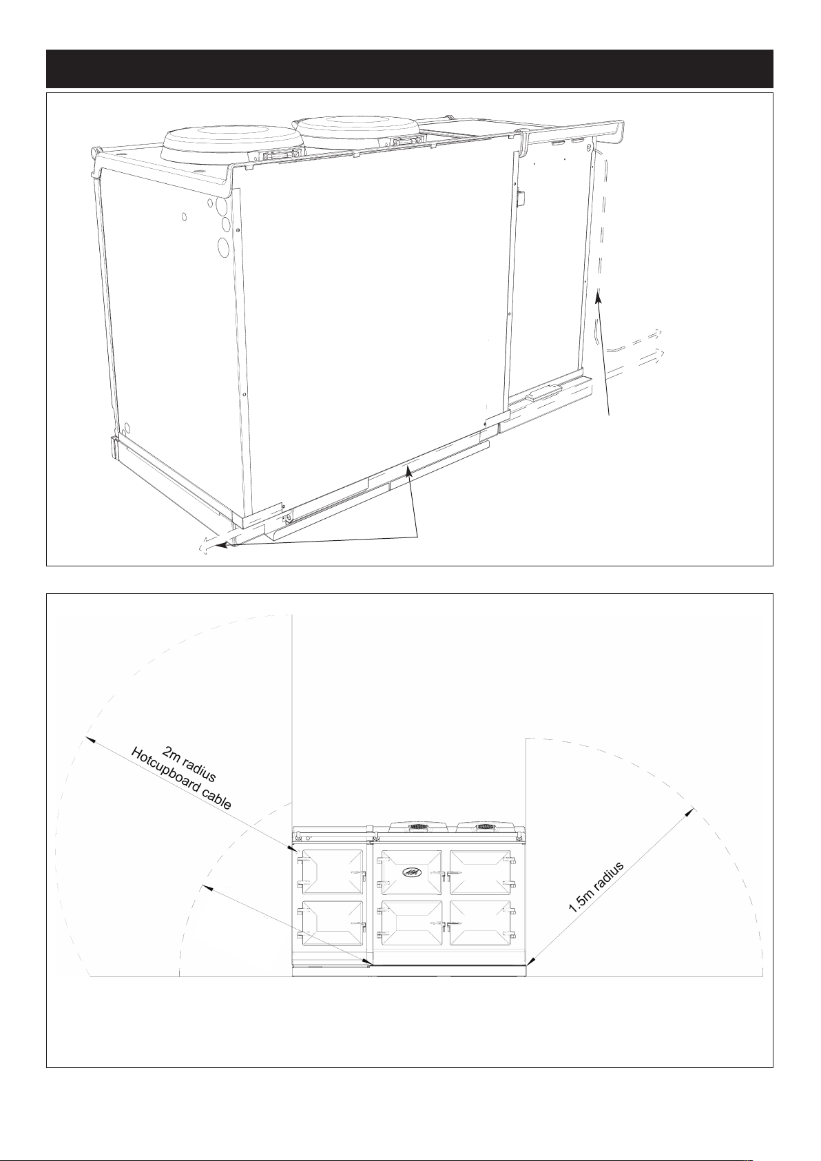
MAINS CABLE ROUTING - AGA DC5G (HOTCUPBOARD)
Fig. 5 DESN 516644
AINS CABLE FED FRO CONTROL
TRAY LEFT OR RIGHT EXIT
THROUGH DUCTING DEPENDENT
UPON POSITION OF SUPPLY SOCKET
Fig. 5A DESN 516447
THE AINS SUPPLY CONNECT POINT UST BE WITHIN THE ZONES SHOWN
HOTCUPBOARD
POWER SUPPLY
10
1.2m radius
AGA DC3
cable
Other manuals for Dual Control Series
1
This manual suits for next models
2
Table of contents
Other AGA Oven manuals

AGA
AGA TC3 Installation instructions

AGA
AGA GC3 (P/F) User manual

AGA
AGA DC3G User manual

AGA
AGA GC Open Flue Range User manual

AGA
AGA Rangemaster Nexus SE 110 Induction Instruction Manual

AGA
AGA 13 AMP RETRO-FIT WITH AIMS User manual

AGA
AGA DC5G User manual

AGA
AGA RAYBURN 600K User manual

AGA
AGA GC 3 Use and care manual

AGA
AGA SIX-FOUR SERIES - DC6 User manual


