
Aerohive AP1130 User manual

© 2014, Aerohive Networks, Inc.
All rights reserved.
P/N 330076-02 1
Aerohive 5 GHz Directional Antenna Installation Guide
This guide explains how to install a 5 GHz directional antenna and connect it to AP170 or AP1130 outdoor
access points. These antennas are designed to be installed in pairs within line-of-sight of each other. When
planning your installation, make sure that there are no obstructions in the line-of-sight space between the
antennas, and that there are no metal objects within 5 feet, (1.5 meters) of either side of the antennas.
Kit Contents, Required Accessories, and Tools
The Aerohive 5 GHz directional antenna kit (AH-ACC-170-ANT-18 for the AP170, or AH-ACC-1130-ANT-18 for
the AP1130) includes the following items:
•5 GHz 18-dBi antenna
•(4) 3/8” (10 mm) hex nuts
•(4) 3/8” (10 mm) locking washers
•(4) 3/8” (10 mm) flat washers
•Mounting bracket
•Bracket hardware: (4) 5/8” (16 mm) hex nuts, (4) 1/2” (12.7 mm) locking washers, and (4) 5/8”
(16 mm) flat washers
•(2) 5’ (1.5 m) RF coaxial cables
To install this antenna, you will need the following accessories and tools:
•Drive sockets (nut drivers) for 3/8” (10 mm) and 5/8” (16 mm) hex nuts
•5/8” (16 mm) open-end wrench to adjust the antenna tilt angle
• RF test meter for 5 GHz devices
Safety Instructions and Site Hazard Warnings
Read and follow these safety instructions and hazard warnings before installing this antenna. Keep these
instructions for future reference.
This antenna is for use in the United States and Canada only.
This antenna is for use in the United States and Canada only.
To comply with radio frequency exposure limits, do not place this antenna within 26" (65 cm) of people.
Make sure that there are no metal objects within 5 feet (1.5 meters) of either side of the antenna.
Make sure there is nothing that obstructs the line-of-sight between antennas.
Make sure there is nothing that obstructs the line-of-sight between antennas.
To install this antenna, you must be a qualified installation professional, licensed or certified in accordance with local regulations.
Use only attachments and accessories specified by Aerohive.

2AP1130 and AP170 5-GHz Directional Antenna Installation Guide
Do not locate the antenna near overhead power lines or other electric light or power circuits, or where it can come into contact
with such circuits. During installation, exercise extreme care not to come into contact with these circuits, which can cause serious
injury or death. For proper installation of the product, refer to national and local electrical codes: NFPA (National Fire Protection
Association) 70, National Electrical Code Article 810 (U.S.); Canadian Electrical Code, Part I, CSA 22.1 and Section 54 (Canada);
and if local or national electrical codes are not available, refer to IEC (International Electrotechnical Commission) 364, Part 1
through 7 (other countries).
Do not connect or disconnect antennas or cables from the AP during periods of lightning activity.

AP1130 and AP170 5-GHz Directional Antenna Installation Guide 3
MOUNTING THE 5 GHZ DIRECTIONAL ANTENNA
Mounting the 5 GHz Directional Antenna
You can mount the 5 GHz directional antenna on a vertical or horizontal mast and adjust the orientation for
optimum radio transmission by tilting the mounting bracket. The mounting bracket accommodates masts
with a 1.5" to 2" (40 - 50 mm) diameter.
To provide unobstructed RF coverage, mount the antenna in a relatively open area on a mast so that it has
at least a three-foot (one-meter) clearance from any nearby obstructions.
After checking that you have all the materials and tools necessary, and familiarizing yourself with the safety
and hazard warnings, you are ready to install the antenna. The installation steps are described below.
Attaching the Antenna Mounting Bracket
The following steps describe how to attach the mounting bracket to the back of the antenna.
1. Attach the bracket for a vertical or horizontal installation as shown below. Use four 1/4” (6.4 mm) flat
washers, locking nuts, and hex nuts to secure the bracket to the antenna chassis.
2. Attach the antenna to a horizontal or vertical mast in one of two ways:
•If you cannot reach a free end of the mast, remove the outer half of the bracket, position the mast
between the two long bolts and re-install the bracket half. Tighten the bracket using a 5/8" (16 mm)
flat washer, locking washer, and hex nut on each bolt.
•If a free end of the mast is accessible, loosen the outer half of the bracket and slide the antenna onto
the mast. Tighten the bracket using a flat washer, locking washer, and large hex nut on each bolt.
The illustration below shows a vertical mast installation.
15
0
15
0
Antenna back
Bracket
Hex nut, locking
washer, and flat
washer
Horizontal mount
Vertical mount
Hex nut, locking
washer, and flat
washer
Mast
Bracket half
Long bolts
Mas
cke
t
b
o
M
Bra
c
L
on
g

4AP1130 and AP170 5-GHz Directional Antenna Installation Guide
Connecting the Antenna to the AP
Use the two antenna cables with N-Male to connect the antenna to the AP, as
shown in the illustration at the left (an AP1130 is shown here). The optimum
distance between the devices should be approximately 3’ (1 m). If there is too
much space between the devices, the signal will degrade. It is not necessary to
ground the antenna.
Aligning the Antenna
Two people are required to test the elevation and alignment for maximum signal
strength. While one person takes readings on an RF test meter, the second
person makes adjustments as necessary by loosening the hex nut on the
mounting bracket and tilting or turning the antenna chassis. Use the angle
markings on the bracket as guidelines, as shown in these illustrations below to
help align the antenna horizontally and vertically as needed.
You can use 2.4 GHz antennas in addition to the 5 GHz directional
antenna. Always install a 50-Ohm load terminator on any unused
antenna connector.
0
15
15
Loosen hex nut to
tilt antenna
Mast
Antenna
Bracket
Loosen hex nut to
rotate antenna
Mast
Antenna
Bracket
Loosen hex nut to
rotate antenna
10 20 30 40 50
10 20 30 40 50
10 20 30 40 50
50 40 30 20 10
0

AP1130 and AP170 5-GHz Directional Antenna Installation Guide 5
DEVICE, POWER, AND ENVIRONMENTAL SPECIFICATIONS
Device, Power, and Environmental Specifications
This section describes the specifications for the 5 GHz directional antenna.
•Frequency range: 5150-5850 MHz
•Bandwidth: 700 MHz
•Gain: 18 dBi
• Width and height: 10" (254 mm), depth: 1.625" (42 mm) without bracket, 8.75" (222 mm) with bracket
• Weight: 2.54 lb (1.15 Kg)
•Polarization: vertical/horizontal
•Maximum power: 20 Watts
•(2) N-type female connectors
•Ethernet connector: autosensing 10/100/1000 Base-T Mbps; compliant with the IEEE 802.3at PoE standard
•Mounting mast diameter: 1.5" - 2" (40 - 50 mm)
•Operating temperature: -40° to 140° F (-40° to 60° C)
•Storage temperature: -40° to 176° F (-40° to 80° C)
• Wind survivability: > 165 mph (266 kph)
•Environmental compliance: IP67
For the latest product documentation, compliance information, and software updates, visit
www.aerohive.com/support.
Other manuals for AP1130
1
This manual suits for next models
1
Table of contents
Other Aerohive Antenna manuals


Popular Antenna manuals by other brands
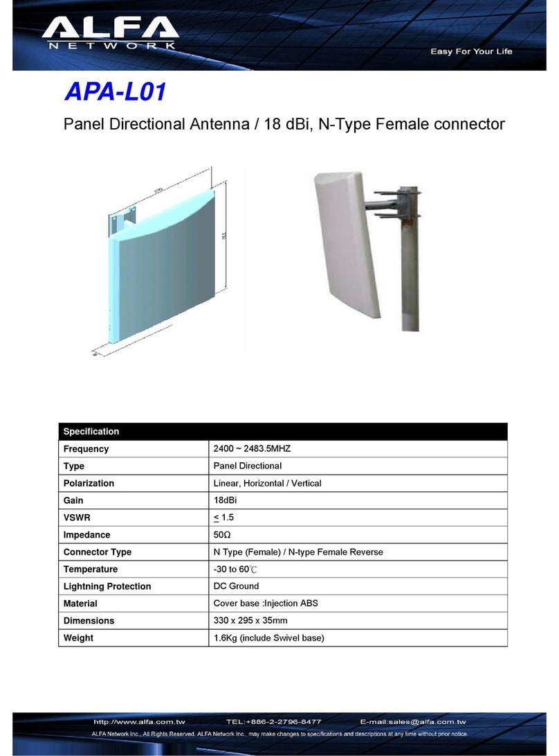
Alfa Network
Alfa Network APA-L01 Specifications

Naval
Naval PR-422CA Operation manual

Feig Electronic
Feig Electronic ID ISC.ANTH200/200 Series manual

TERK Technologies
TERK Technologies TV44 owner's manual
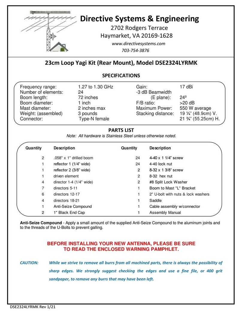
Directive Systems & Engineering
Directive Systems & Engineering DSE2324LYRMK quick start guide

HP
HP J8999A instructions



CommScope
CommScope CMAX-OMFX-43M-I53 Installation instruction

Ramsey Electronics
Ramsey Electronics DAP25 Kit assembly and instruction manual

COBHAM
COBHAM SAILOR 800 VSAT Replacement procedure
Trango Systems
Trango Systems AD900-9 Specification sheet
Steren
Steren ANT-100 user manual

Proxim
Proxim 5054-PA-23 quick start guide