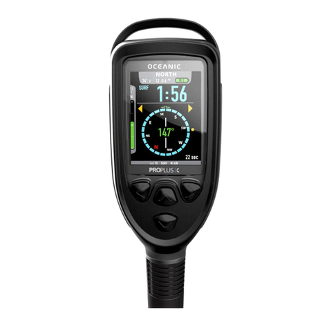
Aeris XR1 User manual

XR1
DIVE COMPUTER
OPERATING MANUAL


3
CONTENTS
LIMITED TWO-YEAR WARRANTY ............................................................................................................................ 5
NOTICES ..................................................................................................................................................................... 5
DECOMPRESSION MODEL ....................................................................................................................................... 5
FULL DISPLAY ............................................................................................................................................................ 6
FEATURES AND DISPLAYS............................................................................................. 7
INTRODUCTION .......................................................................................................................................................... 8
CONTROL BUTTON ................................................................................................................................................... 8
BAR GRAPHS ............................................................................................................................................................. 9
Nitrogen Loading Bar Graph (NiBG) ...................................................................................................................... 9
Variable Ascent Rate Indicator (VARI) .................................................................................................................. 10
INFORMATIONAL DISPLAYS ................................................................................................................................... 10
Depth Displa s ...................................................................................................................................................... 10
Time Displa s ....................................................................................................................................................... 11
Date Displa ......................................................................................................................................................... 11
Temperature Displa ............................................................................................................................................. 11
POWER SUPPLY ...................................................................................................................................................... 12
Batter Indication ................................................................................................................................................... 12
Low Batter Condition ........................................................................................................................................... 13
DIVE TIME REMAINING ........................................................................................................................................... 1
NOTICE - WET ACTIVATION .................................................................................................................................... 16
SETUP AND ACTIVATION .............................................................................................. 17
ACTIVATION .............................................................................................................................................................. 18
SURFACE SEQUENCE ............................................................................................................................................. 19
SURFACE MODE ...................................................................................................................................................... 19
DIVE PLANNER (PLAN MODE) ............................................................................................................................... 20
SET MODE ................................................................................................................................................................ 20
PC INTERFACE ......................................................................................................................................................... 2

4
CONTENTS (continued
DIVE MODES .................................................................................................................. 25
DIVE MODE BAR GRAPHS ...................................................................................................................................... 26
CONTROL OF DISPLAYS ......................................................................................................................................... 26
NO DECOMPRESSION DIVE MODE ....................................................................................................................... 27
DECOMPRESSION DIVE MODE .............................................................................................................................. 29
VIOLATION MODES .................................................................................................................................................. 31
USER SELECTED DIGITAL GAUGE MODE ............................................................................................................ 36
POST DIVE MODES ....................................................................................................... 37
POST DIVE SURFACE MODE .................................................................................................................................. 38
TRANSITION PERIOD .............................................................................................................................................. 38
AFTER THE TRANSITION PERIOD (THE FIRST 2 HOURS) .................................................................................. 39
Time to Fl / Desaturate ....................................................................................................................................... 39
Dive Planner ......................................................................................................................................................... 40
Log Mode .............................................................................................................................................................. 40
AFTER THE FIRST 2 HOURS .................................................................................................................................. 3
RESET FEATURE......................................................................................................................................................
GENERAL ....................................................................................................................... 45
CARE AND CLEANING ............................................................................................................................................. 6
INSPECTIONS AND SERVICE ................................................................................................................................. 7
BATTERY REPLACEMENT ...................................................................................................................................... 58
ALTITUDE SAMPLING/COMPENSATION ............................................................................................................... 53
SPECIFICATIONS ..................................................................................................................................................... 5
SERVICE RECORD ................................................................................................................................................... 58
Pay special attention to items marked with this WARNING symbol.

5
LIMITED TWO-YEAR WARRANTY
For details, refer to the Product Warranty Registration Card provided.
COPYRIGHT NOTICE
This Owners Guide is copyrighted, all rights are reserved. t may not, in whole or in part, be copied, photo-
copied, reproduced, translated, or reduced to any electronic medium or machine readable form without prior
consent in writing from AER S / 2002 Design.
XR1 Operating Manual, Doc. No. 12-7197
© 2002 Design, 2005
San Leandro, CA USA 94577
TRADEMARK NOTICE
AER S, the AER S logo, XR1, and the XR1 logo are all registered and unregistered trademarks of AER S.
Those Trademarks Registered are Registered in the U.S. Patent and Trademark Office. All rights are reserved.
PATENT NOTICE
U.S. Patents have been issued, or applied for, to protect the following design features:
Dive Time Remaining (U.S. Patent no. 4,586,136), Data Sensing and Processing Device (U.S. Patent no.
4,882,678), and Ascent Rate ndicator (U.S. Patent no. 5,156,055). User Setable Display (U.S. Patent no.
5,845,235) is owned by Suunto Oy (Finland).
DECOMPRESSION MODEL
The programs within the XR1 simulate the absorption of nitrogen into the body by using a mathematical
model. This model is merely a way to apply a limited set of data to a large range of experiences. The XR1
dive computer model is based upon the latest research and experiments in decompression theory. Still, using
the XR1, just as using the U.S. Navy (or other) No Decompression Ta les, is no guarantee of avoiding de-
compression sickness, i.e. the ends. Every divers physiology is different, and can even vary from day to
day. No machine can predict how your body will react to a particular dive profile.

6
XR1 FULL LCD
Components:
a. Control Button
b. Variable Ascent Rate Indicator
c. Nitrogen Loading Bar Graph
d. Icon - Max Depth (Log Mode)
e. Icon - Temperature
f. Icon - Dive Number
g. Icon - Max Depth (Dive Mode)
h. Icon - Descend Arrow
Icon - Decompression Ceiling
Icon - Ascend Arrow
i. Icon - Log Mode
j. Icon - Depth units
k. Icon - Time
g. Batter Status Indicator
n. Icon - Operating Mode
a
b
c
d
e
f
g
h
i
k
l
j
m

7
FEATURES and DISPLAYS
WARNING: Prior to diving with the XR1, you must also read and
understand the AERIS Dive Computer Safety & Reference Manual,
Doc. No. 12-7203, which provides Important Warnings and Safety
Recommendations as well as general product information.

8
INTRODUCTION
Welcome to AERIS and thank you for choosing the XR1 !
It is extremely important that you read this O ner's Guide in se-
quence and understand it completely before attempting to use the
XR1.
Remember that technology is no substitute for common sense, and
a dive computer only provides the person using it ith data, not the
kno ledge to use it.
The XR1 has numerous features that are described throughout this
manual.
CONTROL BUTTON
The Control Button (Fig. 1) allo s you to select display options
and access specific information hen you ant to see it.
Fig. 1 - Control Button
R
E
S
P
O
N
S
I
B
L
E
D
I
V
E
R
Be a -
RESPONSIBLE DIVER
at all times.

9
BAR GRAPHS
Nitrogen Bar Graph
The Nitrogen Bar Graph (Fig. 2a) represents tissue loading of ni-
trogen, sho ing your relative no decompression or decompression
status.
The Nitrogen Bar Graph monitors 12 different nitrogen compart-
ments simultaneously and displays the one that is in control of your
dive.
As your depth and elapsed dive time increase, segments ill add to
the Graph, and as you ascend to shallo er depths, the Bar Graph
ill begin to recede, indicating that additional no decompression
time is allo ed for multilevel diving.
It is divided into a gray No Decompression (normal) zone, a yello
Caution zone (also No Decompression), and a red Decompression
(danger) zone.
While you cannot provide a guarantee against the occurrence of de-
compression sickness, you may choose your o n personal zone of
caution based upon age, physique, excessive eight, etc., to reduce
the statistical risk.
Fig. 2 - NiBG
a

10
Variable Ascent Rate Indicator (VARI
The Variable Ascent Rate Indicator (Fig. 3a) provides a visual rep-
resentation of ascent speed (i.e., an ascent speedometer). Gray is a
'normal' rate, yello a 'caution' rate, and red is 'Too Fast'. The seg-
ments of the VARI represent t o sets of speeds hich change at a
reference depth of 60 feet (18 meters). Refer to the chart for seg-
ment values.
WARNING: At depths greater than 60 feet (18 m ,
ascent rates should not exceed 60 fpm (18 mpm .
At depths of 60 feet (18 m and shallower, ascent
rates should not exceed 30 fpm (9 mpm .
INFORMATIONAL DISPLAYS
Depth Displays
During a dive, the Current Depth display (Fig. 3b), indicates
Depths from 0 to 330 feet (99.9 meters) in increments of 1 foot (.1
meter). The Depth range is extended to 399 feet (120 meters)
hen it is set to operate in Digital Gauge Mode.
By pressing the button, the Maximum Depth reached during that
dive ill be displayed (Fig. 3c).
During a Decompression Dive, the required Ceiling Stop Depth is
displayed in the Max Depth position.
Fig. 3 - VARI & Depth
a
60 feet (18 m) & Shallower
Segments Ascent Rate =
Displayed FPM MPM
0 0-10 0 - 3
1 11-25 3.5-7.5
2 26-30 -9
3 >30 >9
Deeper than 60 feet (18 m)
Segments Ascent Rate =
Displayed FPM MPM
0 0-20 0 - 6
1 21-50 6.5-15
2 51-60 15.5-1
3 >60 >1
VARI Values
b
c
Table of contents
Other Aeris Diving Instrument manuals