ABB KSONIK MICRO Administrator Guide
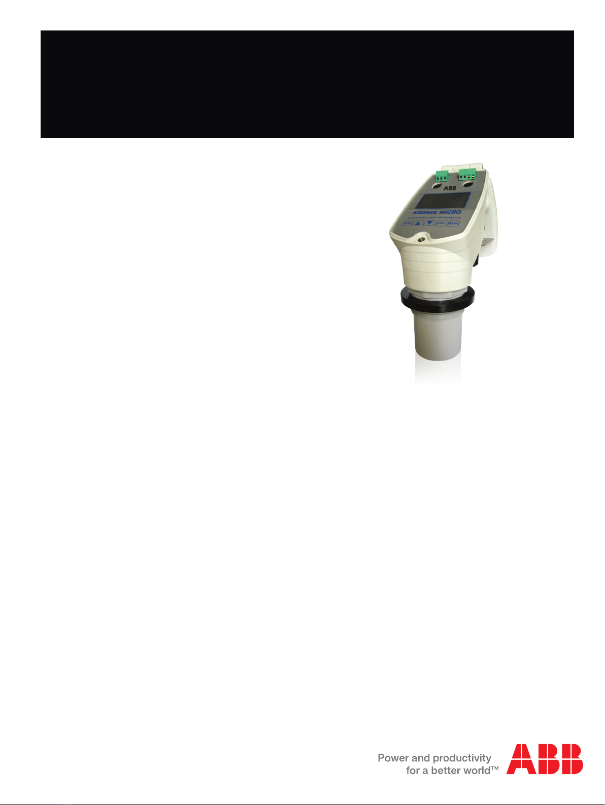
KSONIK MICRO
Ultrasonic Level Transmitter
Operation instruction manual OI/KMICRO-EN Rev. B
Ultrasonic level measurement
with GAP technology
K-TEK Products
Introduction
This operation instruction manual provides the following
information:
–Quick start instructions for distance, level and flow - see
page 3
–Installation procedures - see page 6
–Instructions on how to change parameters - see page 8
–Configuration guidelines for distance/level - see page 9

2KSONIK MICRO Ultrasonic Level Transmitter | Operation instruction manual
Table Of Contents
1.0 Introduction.............................................................................................................................................................3
2.0 Quick Start for Distance..........................................................................................................................................3
3.0 Quick Start for Level...............................................................................................................................................4
4.0 Quick Start for Flow................................................................................................................................................4
5.0 Changing Parameters.............................................................................................................................................5
6.0 Installation ..............................................................................................................................................................6
7.0 Key Descriptions.....................................................................................................................................................8
7.1 Security Code.................................................................................................................................................8
8.0 Conguration Distance / Level................................................................................................................................9
8.1 Distance / Level Mode..................................................................................................................................10
8.2 Conguration Flow........................................................................................................................................14
8.3 Flow Mode....................................................................................................................................................15
9.0 Working with Key Pad in Run Mode.....................................................................................................................19
10.0 Run Mode Screen in Distance / Level Mode ........................................................................................................19
11.0 Onscreen KSCOPE ..............................................................................................................................................20
12.0 Examples..............................................................................................................................................................21
12.1 Distance Measurement...............................................................................................................................21
12.2 Level Measurement....................................................................................................................................21
12.3 Level Measurement and Engineering Units................................................................................................22
12.4 Level Measurement Using the Lineariser Function ....................................................................................22
12.5 Level Measurement Using the Lineariser Function with Non-Linear Vessel ..............................................23
12.6 Venturi Flume .............................................................................................................................................24
12.7 V-Notch.......................................................................................................................................................24
12.8 Working with the Simulator.........................................................................................................................25
13.0 Fault Finding.........................................................................................................................................................26
14.0 Terminal Connections ...........................................................................................................................................27
15.0 RMA Form ............................................................................................................................................................28
16.0 Declaration of Conformity.....................................................................................................................................29
17.0 Warranty ...............................................................................................................................................................30
Operation instruction manual |KSONIK MICRO Ultrasonic Level Transmitter 3
The KSONIK MICRO works on the non-contact principle of ultrasonics.
A pulse of energy emits from the Transducer at the speed of sound and
is detected on its return. The Transmitter can distinguish the difference
between the correct echo and other ambient noise. When the signal
returns, the KSONIK MICRO measures the time period, and then
knowing the speed of sound, it can accurately calculate the distance
from the material to the Transducer. The KSONIK MICRO will adjust the
4-20mA output, accordingly.
In distance mode, the KSONIK MICRO measures distance from the
transducer. This means the 20mA will be the furthest point and the 4mA
will be the closest point.
In level mode, the KSONIK MICRO measures level in a tank. This
means at the furthest point or when the tank is empty, the instrument
will read 4mA. At the closest point the tank will be full and the instrument
will read 20mA.
The Open Channel ow meter uses a level measurement from the
KSONIK MICRO and converts the reading into a ow measurement.
A microprocessor then controls the output functions of the relay, display
and the analogue output signals.
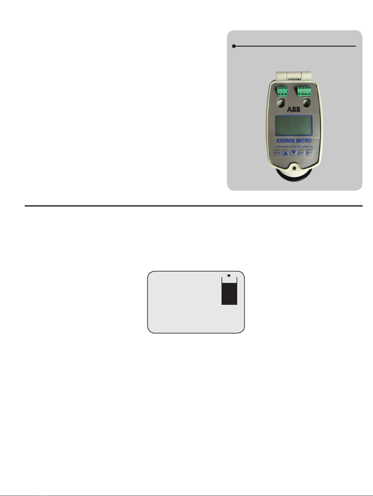
KSONIK MICRO
Ultrasonic Level Transmitter and Switch
2.0 Quick Start for Distance
KSONIK MICRO was designed to be user friendly with a very simple conguration program. This allows the technician to set
up KSONIK MICRO without the aid of a complicated source-code book. There are no references to any codes in KSONIK
MICRO. The set up procedure is all menu-driven with the aid of questions and multiple-choice answers.
Aim the transducer at a wall about 2 m away and check the display. It should read the following:
If the reading is above 2.000 m then move the instrument closer to the wall.
If the reading is below 2.000 m then move the instrument away from the wall.
You may now proceed and check other parameters.
1.0 Introduction
Dist. 2.000 m
mA Output: 7.20 mA
Instant: 2.000 m
Temperature: 20°C
Percentage: 20.00%
4KSONIK MICRO Ultrasonic Level Transmitter | Operation instruction manual
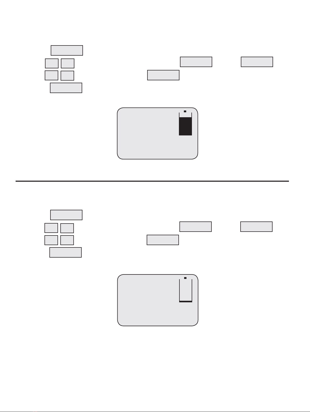
3.0 Quick Start for Level
1. Connect up the power to the instrument described on the KSONIK MICRO face label or in the KSONIK MICRO
manual under terminal connections on page 51.
2. Press
3. Use to get to the default security Code 5159 and then press
4. Use to select level and then press
5. Press
Aim the transducer at a wall about 2.000 m away and check the display. It should read the following:
If the Level reading is below 8.000 m then move the instrument closer to the wall. If the Level reading is above 8.000 m
then move the instrument away from the wall. You may now proceed and check other parameters
4.0 Quick Start For Flow
1. Connect up the power to the instrument as described on the KSONIK MICRO face or in the KSONIK MICRO
manual under terminal connections on page 51.
2. Press
3. Use to get to the default security Code 5159 and then press
4. Use to select level and then press
5. Press
Aim the transducer at a wall about 1.5 m away and check the display. It should read the following:
If the head reading is below 0.500 m or below 64.86 Lt/s then move the transducer closer to the wall. If the head reading
is above 0.500 m or above 64.86 Lt/s then move the transducer away from the wall. You may now proceed and check
other parameters.
SCROLL
▼
▼
ENTER ENTER
ENTER
RUN
▼
▼
Level 8.000 m
mA Output: 17.47 mA
Instant: 2.000 m
Temperature: 20°C
Percentage: 84.21%
Flow: 64.86 Lt/S
T: 00001513408 Lt
Head: 0.500
mA Output: 5.03 mA
Instant: 1.502 m
Temperature: 20°C
Percentage: 6.48%
SCROLL
▼
▼
ENTER ENTER
ENTER
RUN
▼
▼
Operation instruction manual |KSONIK MICRO Ultrasonic Level Transmitter 5
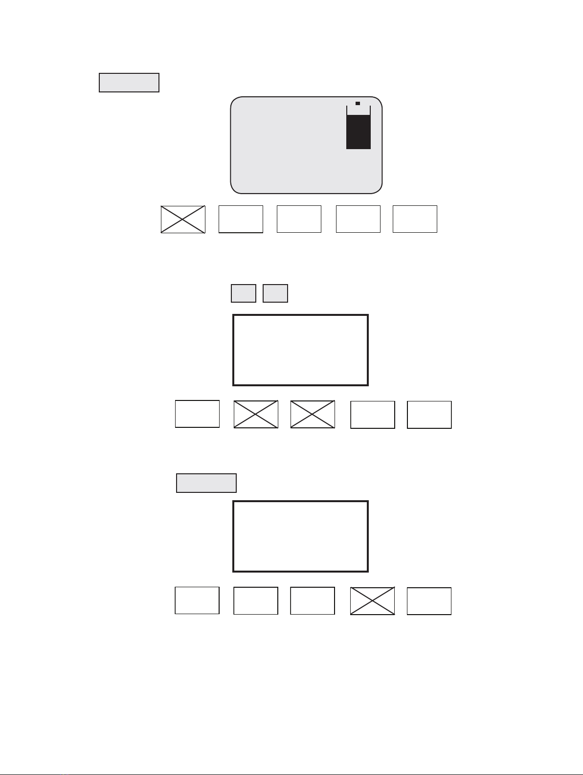
5.0 Changing Parameters
Step 1
Simply press The SECURITY CODE prompt should be displayed.
Step 2
Enter the code 5159 by pressing the keys
Step 3
To conrm security code press
Dist. 2.000 m
mA Output: 7.20 mA
Instant: 2.000 m
Temperature: 20°C
Percentage: 20.00%
SCROLL
Scroll Up Down Enter Run
▼
▼
Scroll Up Down Enter Run
Scroll Up Down Enter Run
Enter the Code:
5000
Enter the Code:
5159
ENTER
6KSONIK MICRO Ultrasonic Level Transmitter | Operation instruction manual
If Code has been accepted, the screen will display
If Code has not been accepted, the screen will display
If the security code has been changed and forgotten then contact the nearest K-TEK agent for override code.
To carry on with programming go to page 16.
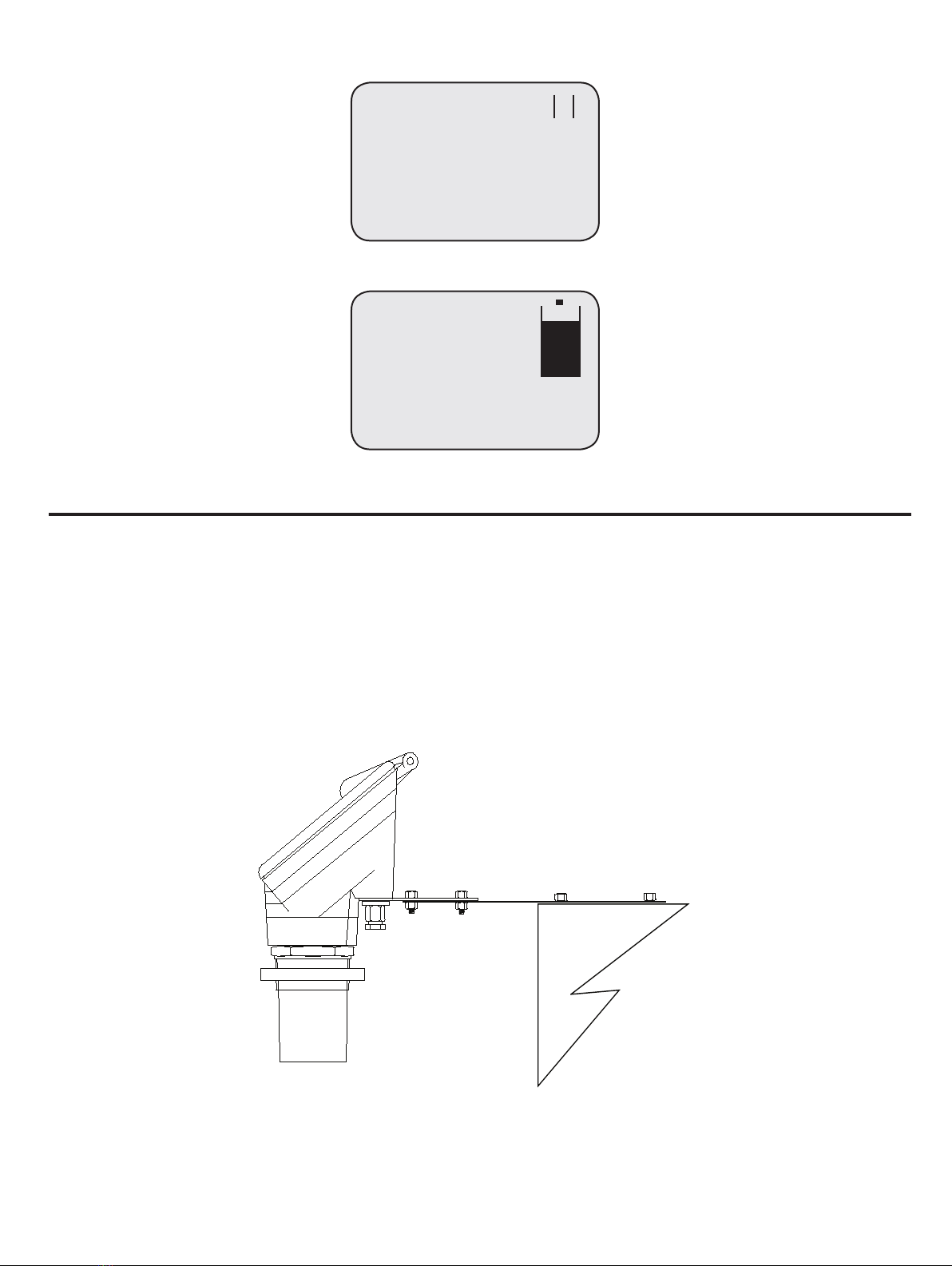
6.0 INSTALLATION
The KSONIK MICRO is protected to IP65. The Transmitter is dust and waterproof so it can be mounted outside. The
KSONIK MICRO should be mounted using the bracket supplied. Do not install the KSONIK MICRO in areas of high vibration
as this may cause failure. Do not install the KSONIK MICRO in the close vicinity of electrical cable, SCR’s or variable speed
drives. The installation of KSONIK MICRO is the most important section of this manual and has been divided up into 6 sub
sections.
1. The KSONIK MICRO must be tted at least 0.50 m / 1.64 ft above the highest point of level.
2. Always use the plastic nut. The KSONIK MICRO must be tted to a rigid support. Use mild steel or a suitable plastic.
Do not use stainless steel as this can cause ringing.
Mode
Dist. Level Flow
Units: Meters
Empty Dist.: 10.000 m
Span: 10.000 m
Blanking: 0.500 m
Rate: 1.0 m/min
Application: Liquids
2
Dist. 2.000 m
mA Output: 7.20 mA
Instant: 2.000 m
Temperature: 20°C
Percentage: 20.00%
Steel bracket with
4 screws for mounting
Wall
Operation instruction manual |KSONIK MICRO Ultrasonic Level Transmitter 7
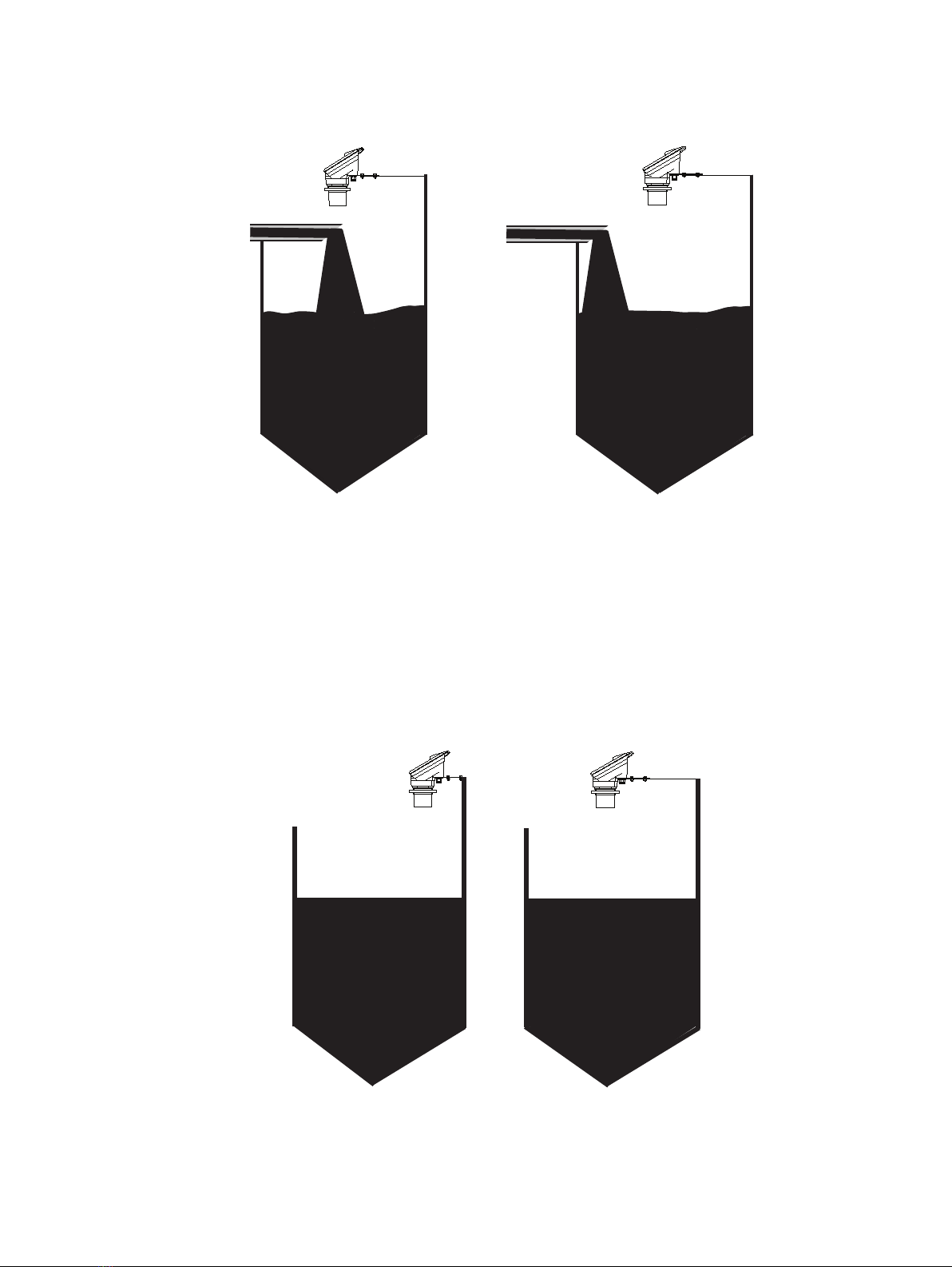
3. The KSONIK MICRO must be perpendicular to the material it is measuring with a clear line of sight and must not be
above beams or lling points.
4. The transducer should be perpendicular to liquid level.
5. If the KSONIK MICRO is in a coned vessel, it must be positioned over the cone. This ensures that the Transducer
receives the true echo and not one from the sides of the cone.
INCORRECT CORRECT
THIS IS INCORRECT AS THE
FILLING POINT IS OBSCURING
THE KMICRO’S LINE OF SIGHT
THIS IS CORRECT AS THE FILL-
ING POINT IS NOT OBSCURING
THE KMICRO’S LINE OF SIGHT
INCORRECT CORRECT
8KSONIK MICRO Ultrasonic Level Transmitter | Operation instruction manual
SCROLL
▼
ENTER
RUN
▼
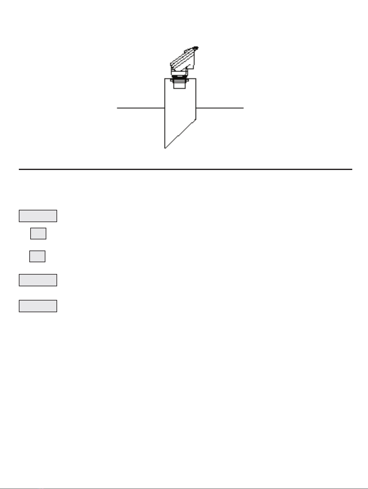
6. When a standpipe is being used it must be as wide as possible; i.e. the pipe diameter must be at least half its
height, preferably made of plastic. The base MUST have a 45° chamfer to reduce the echo size from the bottom of the
standpipe. No welding should be present on the inside of the pipe as this causes false echoes.
7. If any large electrical equipment is installed in the vicinity, then earthed steel conduit must be used.
7.0 KEY DESCRIPTION
KSONIK MICRO is “user friendly” having only 5 keys and a menu driven display. The keys are listed below with their
appropriate functions.
This is used to initially access the programming and then to run through the various menus.
This key is used to INCREASE the value in the various commands. This key also starts the simulation
mode increasing in level. See page 48 for details.
This key is used to INCREASE the value in the various commands. This key also starts the simulation
mode decreasing in level. See page 48 for details.
When a value has been changed it is only accepted by pressing the ENTER key. The ENTER key while
in run mode scrolls through the relay status screen and onscreen KScope screen.
See page 32 for details.
When programming is complete, press RUN to return KSONIK MICRO back to the run mode.
7.1 Security Code
To advance to the programming mode the correct security code must be entered. The factory default code is 5159. This
code can be changed in the programming mode. If you forget the security code please contact your local ABB agent for
the override code.
Operation instruction manual |KSONIK MICRO Ultrasonic Level Transmitter 9
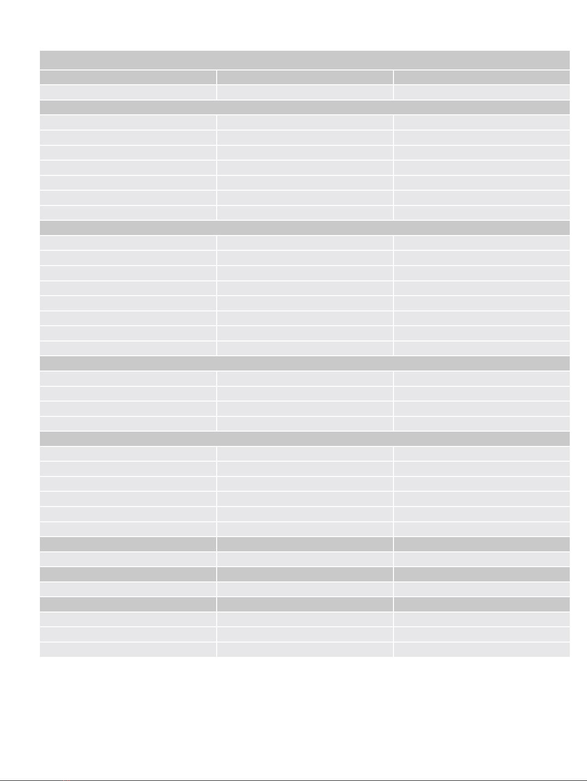
8.0 CongurationDistance/Level
FLOW MODE
BASIC OPTIONS DEFAULTS
SECURITY CODE 0-9999 5159
MODE DISTANCE/LEVEL/FLOW DISTANCE
UNITS METERS/FEET METERS
EMPTY DISTANCE 0.4-15.00 m 10 m
SPAN 0.1-15.00 m 10 m
BLANKING 0.3-14.90 m 0.50 m
RATE OF CHANGE 0.01-20.0 m/min 1.00 m/min
APPLICATION LIQUIDS/SOLIDS LIQUIDS
FACTORY RESET NO/YES NO
TEMPERATURE COMPENSATION OFF/ON OFF
SIMULATE NO/YES NO
SET PASSWORD NO/YES NO
BACKLIGHT OFF/ON (1-60MIN) / PERM 2 MIN
LOSSTIME 30-900SEC 300SEC
LOGTIME 3.6mA, 4.0mA, 20mA, 21mA, HOLD HOLD
FAILSAFE 3.6mA, 4.0mA, 20mA, 21mA, Hold Hold
FAILSAFE
ENGINEERING UNITS NONE, aaa-zzz, AAA-ZZZ,0-9 NONE
MAXIMUM VALUE 0-99999 10000
DECIMAL POINT 0-3 2
ZERO OFF SET -50 mm TO 50 mm 0
SETUP RELAY NO/YES NO
RELAY OFF/LO/HI OFF
SETPOINT SPAN 0 m
RESET POINT SPAN 0 m
PUMP CYCLE OFF/FIFO/ROTATE OFF
CLEAR RELAY NO/YES NO
SETUP LINEARISER NO/YES NO
ACTIVATE LINEARISER NO/YES NO
SETPOINT 1-21 1
HEIGHT 0m-SPAN 0 m
PERCENTAGE 0-100% 0%

10 KSONIK MICRO Ultrasonic Level Transmitter | Operation instruction manual
8.1 Distance/LevelMode
SECURITY CODE
Security code to advance to programming.
DEFAULT 5159
MODE
Choose between Distance, Level.
DEFAULT Distance
UNITS
Choose between Feet and Meters.
DEFAULT Meters
EMPTY DISTANCE
This is the distance from the face of the transducer to the bottom of the tank.
DEFAULT 10.00 m
SPAN
This gure is the measuring range of the instrument i.e. distance from the bottom of the tank to the highest point being
measured. Remember, the material must not approach within 0.50 meters of the transducer face or within the blanking
distance of the transducer.
DEFAULT 10.00 m
BLANKING
This is the area where an echo cannot be processed because the return echo would be received while the transducer
is still ring.
DEFAULT 0.50 m
RATE OF CHANGE
This is used to set up the rate of change of the level output. The rate of change governs the rate at which the instrument
output change. By increasing the rate of change (4.00 m/min) it will allow the KSONIK MICRO to monitor rapid changes
in level. If the level moves faster than 1 m/minute in measurement increase the rate of change. If a more stable output is
required decrease the rate of change (0.30 m/min).
DEFAULT 1.00 m/min
APPLICATION
This selection can be used to select either liquid or solid applications. The solid application will provide more power to
locate the correct echo.
DEFAULT Liquids
FACTORY RESET
This prompt will reset all values entered back to factory setting except the password. Please write down all settings be-
fore using this function.
DEFAULT No
TEMPERATURE COMPENSATION
Sets temperature compensation on or off.
DEFAULT Off
SIMULATE
Simulates the level, relay outputs and mA outputs with the rate of change, selected.
DEFAULT No
SET PASSWORD
Table of contents
Other ABB Transmitter manuals


Popular Transmitter manuals by other brands


Rosemount
Rosemount 4600 Reference manual

Speaka Professional
Speaka Professional 2342740 operating instructions

trubomat
trubomat GAB 1000 instruction manual

Teledyne Analytical Instruments
Teledyne Analytical Instruments LXT-380 instructions

Rondish
Rondish UT-11 quick start guide

MG
MG 10JRE instruction manual


