ABB Infinity S J5964803 L209 User manual

QUICK START GUIDE
Page 1
© 2021 ABB. All rights reserved.
Infinity S 19" Universal Power Shelf
Models: J5964803 L209-L216
• Sockets - 5/16”, 7/16”, etc.
• Screwdrivers - Philips #1 and #2, Flat small
Inter-Shelf Bracket
Step 2 - Connect Chassis Ground
Lug Landings: #10 double-hole on 5/8-inch center
(lugs not provided)
Some applications may rely on frame mounting
screws for shelf ground omitting the chassis ground
cable.
Minimum 10 AWG wire is recommended.
Torque 10-32 screws to 30 in-lb (3.4Nm) - 5/16”
socket. Knockout
2 Adjacent Shelves
Mounting Ears
Chassis Ground
AC Wiring Box
Tools required
• Wire cutters and strippers
• Cable crimpers
• Torque wrench - 0-65 in-lb (0-10Nm)
Step 1 - Mount Shelf
1. Reposition mounting ears as required - 4 screws
each. Torque to 25 in-lb (2.8Nm) - Phillips
screwdriver.
2. Install Inter-Shelf brackets between adjacent
shelves (optional). Torque to 25 in-lb (2.8Nm) - Philli
screwdriver
3. Attach shelf to the frame using a minimum of four
screws (two on each side) - 12-24 (provided). Torque
to 35 in-lb (4Nm) - 5/16” socket.
Universal Power Shelves accept +24V and –48V rectifiers and converters.
Primary shelf (L209, L211, L213, & L215) includes controller slot. Install shelf immediately below distribution, if used.
Expansion shelf (L210, L212, L214, & L216) includes cables and hardware to connect to an adjacent shelf.
No vertical spacing is required. Provide 2 inch minimum clearance at back of shelf for rectifier airflow.
Refer to Infinity S Flex Power System Brochure for details and accessories.
-

QUICK START GUIDE
Page 2
© 2021 ABB. All rights reserved.
AC Cords - AC3
AC receptacles for each rectifier are on the rear (no AC wiring box).
Connect 120V~ / 200-240V~ , 50-60Hz AC cords with C19 receptacle to each
shelf AC connector - see Information: AC Cord Options.
Terminal Block - AC5, AC6, AC7
AC terminal block is in the AC box on the rear.
Connect 120V~ / 200-240V~ / 277V~, 50-60Hz AC to the detachable input terminal block in wiring box - knockout
for 3/4” conduit or cord grip.
1. Strip and Torque - see below
2. Pull on wires to verify secure connection.
Step 4 - Connect DC Output
Connections are on the rear under covers.
Note:
Single voltage systems require +24V OR –48V connections.
Dual voltage systems require +24V AND –48V connections.
Bus Connection - to adjacent shelf
Install inter-shelf buses joining +24V, -48V, and
RETURN outputs of adjacent shelves.
Torque to 65 in-lb (7.3 Nm)
Cable Connection - to stand-alone shelf
Lug Landings - 2 x 1/4” on 5/8” center, 0.7” (18mm) max. tongue width.
Connect cables with suitable lugs to +24V, -48V, and RETURN.
Torque to 65 in-lb (7.3 Nm)
Step 3 - Connect AC Input
External Feed Protector - see Information: Rectifier Options
Danger: Turn OFF and lock-out tag-out the AC source before making AC connections.
Follow all local and national wiring rules.
List Rectifiers per Feed
AC3 - IEC320 C20 Receptacles- 1-phase
AC6 - Terminal Block - 3-phase delta
AC7 - Terminal Block - 3-phase wye
AC6
delta
AC3
1-phase
Strip - 10 mm Torque - 7 in-lb (0.75 Nm)
3-phase
Strip-12 mm
Torque - 16 in-lb (1.75 Nm)
AC7
wye
-48V Connections
covers removed
Inter– shelf
bus
Dual Lug Landings
RETURNs covers
shown
2 Adjacent Shelves
AC5
AC
Input
211,212
215,216
ACS
-Terminal Block
-1-phase
213,214
209,210
1
1
3
3
Jl
1111
11111,1,
AWGmax
10
6
6

QUICK START GUIDE
Page 3
© 2021 ABB. All rights reserved.
CAUTION: Verify battery voltage and polarity with a voltmeter before proceeding.
Note: RETURN must be externally connected to DC Reference (CO) ground.
Note: External DC protectors must be installed in the non-grounded (non-RETURN) side of the DC path.
Step 5 - Set Controller Jumpers - Primary Shelf Only
Set LAN Port and Relay per Galaxy Pulsar Edge Controller Quick Start Guide
Step 6 - Install Controller - Primary Shelf Only
Install Controller in shelf controller slot per Galaxy Pulsar Edge Controller Quick Start Guide
Step 7 - Set Shelf Switches
Shelf Switches are on rear - figure above.
SW1 - Set Rectifier output voltage for shelf: 48V or 24V.
SW2 - Set Shelf Number: 1 for 1st shelf, 2 for 2nd shelf, etc.
Note: ID conflict alarm will occur if two shelves are set to same number.
Step 8 - Install Signal and Communications Cables
Connectors are on rear - figure above.
1. J1 Alarms - office alarms and signals. See Information: Alarm Connections.
2. J3-4 Shelf-to-Shelf communication - Connect adjacent shelves. Connect 1-Wire Battery Temp and Voltage Monitor
(optional).
3. J5 LAN - Connect to Ethernet network.
4. J7 Distribution Panel signals - Connect to Distribution Panel if present.
Step 9 - Install 1-Wire Battery Temp and Voltage Monitor per Galaxy Pulsar Edge
Controller Quick Start Guide - Optional
1. Connect 1-Wire Battery Temp and Voltage Monitor to upper J3/J4 connector on Rectifier Shelf with controller.
USB Craft Port
Shelf to Shelf Distribution
signals cables
SW2 Shelf ID Switches
SW1 Output
Voltage Switch
1-Wire Battery Temp Monitor
J5 LAN Port
Shelf to Shelf cable
Distribution Shelves if present
Primary Rectifier Shelf with
controller
Expansion Rectifier Shelf
without controller
if present
J1 Alarm Inputs and Outputs
Signal Connection and Shelf ID Switches
Jl
1111
11111,1,
QUICK START GUIDE
Page 4
© 2021 ABB. All rights reserved.
Step 11 - Initial Start Up
1. Verify that all AC, DC and Alarm connections are complete and secure.
2. Turn on AC input breakers.
3. If there are no alarms, make required adjustments to the default settings on the controller for this installation.
Step 12 - Configure Controller per Galaxy Pulsar Edge Controller Quick Start
Guide
Verify and edit controller basic configuration parameters per site engineering instructions.
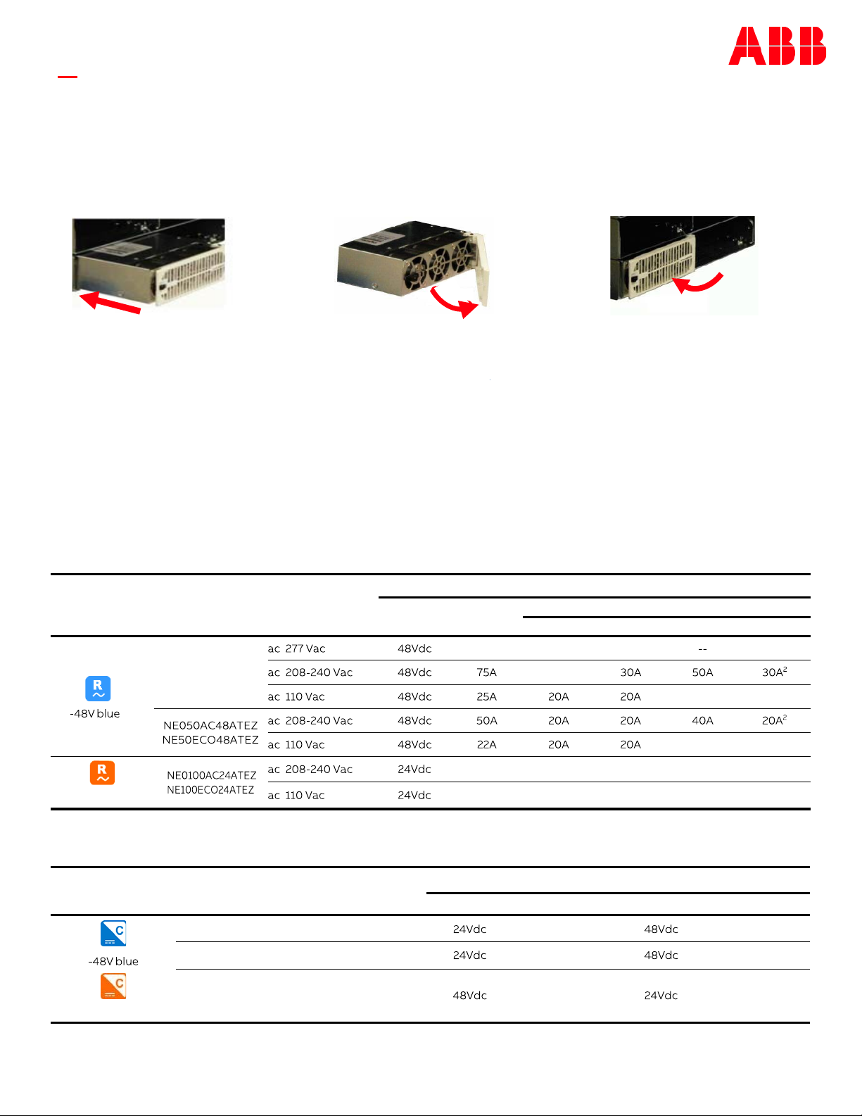
Information: Rectifier and Converter Options
Step 10 - Install Rectifiers and Converters
.
Rectifier
Input
Output DC Recommended AC Breaker
Voltage Current 1-Phase 3-phase
AC3 AC5 AC6 - delta AC7 - wye
NE075AC48ATEZ
75A 25A 25A1
+24V Orange
100A 20A 20A 40A 20A2
44A 20A 20A
Converter
Input DC Output DC
Voltage Current3Voltage Current
NE030DC48A 81A max 75A
NE040DC48A 108A max 50A
+24V Orange
NE075DC24A 54A max 100A
Open the faceplate by sliding the
faceplate latch to the left until the
faceplate releases and swings
outward.
Slide the unit into the slot until it engages with
the back of the shelf. Swing the faceplate closed
to fully seat the unit. Verify the faceplate is
latched.
1. 480 Vac Line to Line
2. 380 Vac Line to Line
3. Maximum current at full load and end of discharge voltage ( 21Vdc or 42Vdc )
Slide the unit into the slot
approximately 3/4 of the way
ac
277Vac
48Vdc
ac
208-240
Vac
48Vdc
B
ac
novae
48Vdc
-48Vblue
ac
208-240
Vae
48Vdc
NE050AC48ATEZ
NESOECO48ATEZ
ae
novae
48Vdc
ll
NE0100AC24ATEZ
ac
208-240
Vac
24Vdc
NE100EC024ATEZ
ae
novae
24Vdc
-48Vblue
75A
30A
25A
20A
20A
SOA
20A
20A
2"2A
20A
20A
24Vde
24Vdc
48Vdc
S0A
40A
48Vde
48Vdc
24Vdc
Jl
1111
11111,1,
30A
2
20A
2

QUICK START GUIDE
Page 5
© 2021 ABB. All rights reserved.
IEC Style AC Cords 12 AWG
Part Num
CC848847368 No plug 8 ft
CC848850792 5-15P 8 ft
CC848850801 5-20P 8 ft
CC848850826 6-15P 8 ft
CC848850834 6-20P 8 ft
850044361 L5-15P 15 ft
850044362 L5-20P 15 ft
CC848895961 L6-20P 15 ft
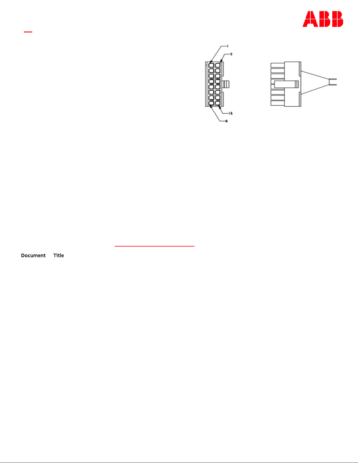
Information: Alarm Connections
See the Infinity S-Flex Power System Brochure for details.
Alarm connections are on the rear of the shelf.
Change alarm descriptions via LAN port (Web pages) or Craft port (EasyView2) when required.
Pin Color Signal1 Default2
User Configurable Alarm Input
White User Configurable Alarm Input Aux Major
Alarm Battery Supply (ABS)
Power Major Relay Return PMJ Return
Power Minor Relay Return
Red/White Relay 1 Return
White/Black
Red User Configurable Alarm Input SPD Fail
Green User Configurable Alarm Input
Power Major Relay
Power Minor Relay PMN
Green/White BD/VLV
White/Red Relay 2 Return
Fuse Alarm Major (FAJ)
1. Relays 1 - 4 are user configurable.
2. Customer specific factory defaults - see the Quick Start Guide Supplement.
3. Positive Temperature Coefficient resistor protected battery voltage provides up to 0.5A for external alarm circuits.
Information: Rectifier and Converter Options
1 Black
2
3
Red/Black
4 Orange
5
Orange/Black
6
7
8 Blue/Red
9
10
11
Blue
12
Green/Black
13
Blue/Black
14
15
16
Orange/Red
Plug
PTC3 Protected
VBUS-/ABS
Relay2
Relay3andRelay4Return
Relay4
Relayl
Relay3
Length
Standard
Factory
DoorOpen
PMN
Return
BD/VLVReturn
AC
Fail
(ACF)
FA.J
and
Relay4Retum
ACFail
Relay4
PMJ
ACF
Return
Jl
1111
11111,1,
QUICK START GUIDE
Page 6
© 2021 ABB. All rights reserved.
Alarm Cables - Reference Only.
See Infinity S Flex Power System Brochure for details.
CC848890161 5 ft
CC848890178 15 ft
CC848890186 50 ft
CC848890194 150 ft
Specifications and Application
• Specifications and Ordering Information – are in brochures listed in Reference Documents.
• External Surge Protective Devices (SPDs) - are required on all AC inputs.
Equipment Safety is Approved in IEC 60664-1 Installation Category II environments.
• Equipment and subassembly ports -
1. are suitable for connection to intra-building or unexposed wiring or cabling;
2. can be connected to shielded intra-building cabling grounded at both ends.
• Grounding / Bonding Network – Isolated Ground Plane (Isolated Bonding Network) or Integrated Ground Plane (Mesh-
Bonding Network, or Common Bonding Network).
• Installation Environment - Network Telecommunication Facilities, OSP, or where NEC applies.
• DC Returns - Isolated DC return (DC-I) or Common DC return (DC-C).
Reference Documents
These documents are available at abbpowerconversion.com
850035894 Galaxy Pulsar Edge Quick Start Guide
CC848815341 Pulsar Edge Controller Family Product Manual
Infinity S Flex Power System Brochure
Document Title
Jl
1111
11111,1,

Page 7
© 2021 ABB. All rights reserved.
We reserve the right to make technical changes or modify the
contents of this document without prior notice. With regard
to purchase orders, the agreed particulars shall prevail.
ABB does not accept any responsibility whatsoever
for potential errors or possible lack of information in this
document.
We reserve all rights in this document and in the subject matter and
illustrations contained therein. Any reproduction, disclosure to third
parties or utilization of its contents – in whole or in parts – is
forbidden without prior written consent of ABB.
Copyright© 2021 ABB
All rights reserved
ABB
601 Shiloh Rd.
Plano, TX USA
abbpowerconversion.com
Jl
1111
11111,1,
This manual suits for next models
7
Table of contents
Other ABB Power Supply manuals

ABB
ABB CP-T 24/20.0 User manual

ABB
ABB GH Q630 7043 P0001 Service manual

ABB
ABB ProcessMaster 500 User manual

ABB
ABB CPS6000-Systems-48V DC Power User manual

ABB
ABB ACS880-207 User manual

ABB
ABB 4234 600 User manual

ABB
ABB CP-E 5/3.0 User manual

ABB
ABB ODPSE230C User manual

ABB
ABB Infinity S User manual

ABB
ABB 4234 600 User manual

ABB
ABB ACS550-01 User manual

ABB
ABB RPB 520 User manual

ABB
ABB PCS100 UPS-I User manual

ABB
ABB ACS880-207LC User manual

ABB
ABB ACS880-304 +A018 User manual

ABB
ABB SV/S 30.160.1.1 User manual

ABB
ABB NES4812-23-AC1-PS4-DC1E-LVBD User manual

ABB
ABB CPS6000 User manual

ABB
ABB CP-E Series User manual

ABB
ABB Infinity S User manual


