ABB TPL65-A30 User manual

Operation Manual
ABB Turbocharging
ABB Turbo Systems Ltd
CH 5401 Baden
Type TPL65-A30 HT843591
nMmax 505 t Mmax 680
nBmax 479 t Bmax 650
1/s °C
01230 35 50 50
Year 2017 made in Switzerland
Application according to
the Operation Manual
kg
HZTL2482 English
TPL65-A30
Original Operation Manual

Operating condition and replacement intervals
The operational limits for the turbocharger nBmax, tBmax, nMmax, tMmax, inspection- and replacement intervals for the compon-
ents concerned on the rating plate are valid for the operational mode and compressor inlet condition, which has been agreed upon
between the engine builder and ABB.
Note: Replacement intervals of components depends on the load profile, turbine inlet temperature, suction air temperature and
turbocharger speed. In case the operation conditions differs significantly from what is considered to be normal for the cur-
rent application, it is recommended to contact ABB for a re-calculation of replacement intervals. Frequent load alterations,
high temperatures and high speed lower the life of components.
Unless otherwise agreed, the application limits nMmax, tMmax are valid for the test operation for a limited time.

Operation Manual / TPL65-A10 / -A30
Table of contents
© Copyright 2018 . All rights reserved. HZTL2482_EN Revision D April 2018
Operation Manual
1 Preliminary remarks................................................................................................. 3
1.1 Purpose of this manual .................................................................................................. 3
1.2 Layout and function........................................................................................................ 4
1.3 Intended use of the turbocharger .............................................................................. 6
1.4 Storage of new turbochargers and spare parts ....................................................... 7
1.5 Essential information..................................................................................................... 9
1.6 Symbols and definitions .............................................................................................. 12
1.7 Turbocharger rating plate ........................................................................................... 13
1.8 Contact information..................................................................................................... 14
2 Safety....................................................................................................................... 15
2.1 Introduction ................................................................................................................... 15
2.2 CE conformity ................................................................................................................ 15
2.3 Definition of mandatory signs ................................................................................... 16
2.4 Definition of Safety instructions ............................................................................... 16
2.5 Warning plates on the turbocharger......................................................................... 17
2.6 Safe operation and maintenance............................................................................... 18
2.7 Hazards during operation and maintenance........................................................... 21
2.8 Periodic checking of the pressure vessel ................................................................. 26
2.9 Lifting loads ................................................................................................................... 26
3 Start-up .................................................................................................................. 28
3.1 Oil supply ........................................................................................................................ 28
3.2 Inspection work............................................................................................................. 31
3.3 Commissioning after taking out of operation........................................................ 33
4 Operation ............................................................................................................... 34
4.1 Noise emissions ............................................................................................................ 34
4.2 Servicing work ............................................................................................................... 36
4.3 Replacement intervals for turbocharger components.......................................... 39
4.4 Speed measurement .................................................................................................... 41
4.5 Stopping the engine .................................................................................................... 44
5 Maintenance .......................................................................................................... 45
5.1 Foreword to Maintenance .......................................................................................... 45
5.2 Cleaning the filter silencer.......................................................................................... 46
5.3 Cleaning the compressor during operation ............................................................ 52
5.4 Cleaning turbine blades and nozzle ring in operation........................................... 56
5.5 Cleaning components mechanically.......................................................................... 61

Operation Manual / TPL65-A10 / -A30
Table of contents
© Copyright 2018 . All rights reserved. HZTL2482_EN Revision D April 2018
6 Troubleshooting.................................................................................................... 70
6.1 Malfunctions when starting........................................................................................ 70
6.2 Surging of the turbocharger....................................................................................... 71
6.3 Malfunctions during operation .................................................................................. 72
6.4 Malfunctions when stopping ...................................................................................... 75
6.5 Speed measurement system ...................................................................................... 76
7 Removal and installation....................................................................................... 77
7.1 Turbocharger weights.................................................................................................. 77
7.2 Removing the turbocharger........................................................................................ 78
7.3 Installing the turbocharger ........................................................................................ 80
8 Disassembly and assembly .................................................................................. 81
8.1 Introduction ................................................................................................................... 81
8.2 Module weights ............................................................................................................. 83
8.3 Removing and fitting filter silencer or air suction branch.................................... 85
8.4 Axial clearance ............................................................................................................... 87
8.5 Removing cartridge group ......................................................................................... 88
8.6 Dismantling and installing the turbine diffuser and nozzle ring ......................... 92
8.7 Installing cartridge group............................................................................................ 95
8.8 Dismantling and fitting nozzle ring at turbine end ............................................... 98
8.9 Table of tightening torques..................................................................................... 100
9 Taking out of operation at short notice .......................................................... 102
9.1 Possibilities for emergency repair........................................................................... 102
9.2 Fit cover plate .............................................................................................................. 102
9.3 Blocking the inlets and outlets................................................................................. 107
9.4 Bypass the turbocharger ........................................................................................... 107
10 Mothballing the turbocharger ........................................................................... 108
10.1 Taking the engine out of operation for up to 12months................................... 108
10.2 Taking the engine out of operation for more than 12months .......................... 110
11 Disposing of turbocharger components........................................................... 111
12 Spare parts............................................................................................................ 112
12.1 Ordering spare parts.................................................................................................. 112
12.2 View of the turbocharger with part numbers ....................................................... 114
12.3 View of turbine cleaning system with part numbers (optional)........................ 116

Operation Manual / TPL65-A10 / -A30
1 Preliminary remarks / 1.1 Purpose of this manual
© Copyright 2018 . All rights reserved. HZTL2482_EN Revision D April 2018
1 Preliminary remarks
1.1 Purpose of this manual
This Operation Manual belongs to the turbocharger with the identical
serial number (01), see the cover sheet of the Operation Manual and the
turbocharger rating plate.
Operation Manual
This Operation Manual enables you to familiarize yourself with the tur-
bocharger supplied by ABB Turbo Systems and to use it as intended.
It provides important information in order that the turbocharger can be
operated safely, correctly and efficiently.
This Operation Manual complements and expands existing national reg-
ulations concerning work safety and accident prevention.
Target group
This Operation Manual is intended for engineers and qualified mechan-
ics who are responsible for operating the engine and the turbocharger
installed on it.
Availability of operation manual
An operation manual must be available at all times at the place where
the turbocharger is used.
Everyone who operates or works on the turbocharger must have first
read and understood the operation manual.
Page 3 / 116
Operation Manual / TPL65-A10 / -A30
1 Preliminary remarks / 1.2 Layout and function
© Copyright 2018 . All rights reserved. HZTL2482_EN Revision D April 2018
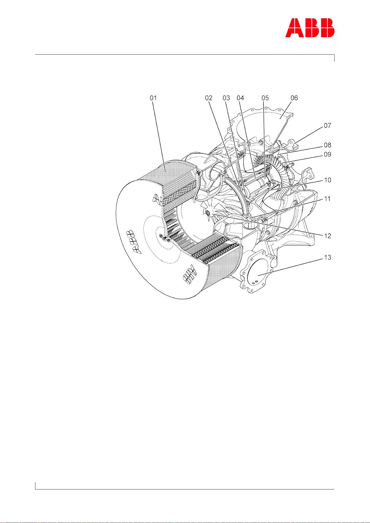
1.2 Layout and function
01Filter silencer 08Nozzle ring
02Radial plain bearing 09Turbine wheel
03Thrust bearing 10Bearing casing
04Bearing bush 11Diffuser
05Radial plain bearing 12Compressor wheel
06Gas outlet casing 13Compressor casing
07Gas inlet casing
Page 4 / 116

Operation Manual / TPL65-A10 / -A30
1 Preliminary remarks / 1.2 Layout and function
© Copyright 2018 . All rights reserved. HZTL2482_EN Revision D April 2018
Mode of operation
The turbocharger is a turbomachine and consists of the following main
components:
¡Turbine
¡Compressor
These are both mounted on a common shaft.
The exhaust gases from the diesel engine flow through the gas inlet cas-
ing (07) and nozzle ring (08) to the turbine wheel.
The turbine wheel (09) uses the energy contained in the exhaust gas to
drive the compressor wheel (12). The compressor then draws in fresh air,
compresses it and then forces it into the cylinders.
The exhaust gases escape to free air through an exhaust gas pipe which
is connected to the gas outlet casing (06).
The air which is necessary for operation of the diesel engine and is com-
pressed in the turbocharger is drawn through the suction branch or the
filter silencer (01) into the compressor wheel (12). This air then passes
through the diffuser (11) and leaves the turbocharger through the com-
pressor casing (13).
The rotor runs in two radial plain bearings (02/05). One plain bearing is
in the bearing bush (04), and the second one is in the axial thrust bearing
(03) at the compressor end.
The plain bearings are connected to a central lubricating oil duct which is
fed with oil from the engine's lubricating oil circuit. The oil outlet is al-
ways at the lowest point of the bearing casing (10).
Page 5 / 116

Operation Manual / TPL65-A10 / -A30
1 Preliminary remarks / 1.3 Intended use of the turbocharger
© Copyright 2018 . All rights reserved. HZTL2482_EN Revision D April 2018
1.3 Intended use of the turbocharger
NOTICE
This turbocharger supplied by ABB Turbo Systems has been developed
for use on diesel engines to generate the volume of air and the char-
ging pressure required to operate the engine.
The engine builder has provided ABB Turbo Systems with information
regarding the intended use of the engine, from which the operating
limits specific to the turbocharger shown on the rating plate (such as
operating speeds, temperatures, exchange intervals / replacement in-
tervals) have been derived.
If it is used in conjunction with a gas engine, the engine must not be in-
stalled in a potentially explosive environment, and precautionary meas-
ures must be taken to ensure that the machine room as a whole is clas-
sified as not potentially explosive.
Any other use will be regarded as a special application which must first
be discussed with ABB Turbo Systems. The manufacturer accepts no li-
ability for other applications. If it is used otherwise, ABB Turbo Systems
reserves the right to reject all warranty claims.
State of the art This turbocharger was built according to state-of-the-art technology
and is operationally safe according to recognised safety regulations.
WARNING
Improper operation and maintenance of the turbocharger can result in
danger to life and limb of the user or third parties. In addition, im-
proper use may cause damage to the machine.
uThe machine may be operated only by trained personnel.
Use of the turbocharger as intended also includes observance of the in-
stallation / fitting, disassembly / removal, operating, maintenance / ser-
vicing and repair conditions specified by the manufacturer. Disposal reg-
ulations set down by local authorities must be observed.
Perfect condition The turbocharger may be installed only when in technically perfect condi-
tion while observing the instructions given in the engine builder's
manual. It may be used only for the intended purpose and operated in
compliance with the operation manual.
uMalfunctions which could affect safety must be eliminated immedi-
ately.
The manufacturer accepts no liability for any damage resulting from un-
authorised alterations to the turbocharger.
Page 6 / 116

Operation Manual / TPL65-A10 / -A30
1 Preliminary remarks / 1.4 Storage of new turbochargers and spare
parts
© Copyright 2018 . All rights reserved. HZTL2482_EN Revision D April 2018
1.4 Storage of new turbochargers and spare parts
Storage of new turbochargers and spare parts up to 6 months
New turbochargers and spare parts from ABB Turbo Systems can be
stored in sealed packaging without additional mothballing measures for
up to 6 months from the date of delivery (marked by the VCI label on the
package).
Volatile Corrosion Inhibitor (VCI)
Only dry rooms in which the relative humidity is between 40…70 % and
no condensation can form are suitable for storage.
Storage of new turbochargers and spare parts for more than 6
months (VCI)
WARNING
Protection of health when handling VCIs
VCI products are not hazardous in the sense of the Hazardous Sub-
stances Ordinance. Nevertheless, the following points are to be ob-
served when handling VCIs:
uEnsure good room ventilation.
uDo not eat, drink or keep food at the workplace while working with
VCIs.
uWear safety gloves.
uClean hands and face after working with VCIs.
uFor further information refer to www.branopac.com.
Wear safety gloves to protect against chemical hazards.
The following mothballing measures are required every 6months:
uOpen the package.
uRemove the VCI corrosion protection emitter from the package and
replace it with a new, identical VCI corrosion protection emitter. New
VCI corrosion protection emitters can be obtained at www.brano-
pac.com.
uDispose of the old VCI corrosion protection emitter in an environ-
mentally compatible manner, professionally and in accordance with
local regulations.
uSeal the package. The better the external seal is designed, the more
permanent the protection.
Page 7 / 116

Operation Manual / TPL65-A10 / -A30
1 Preliminary remarks / 1.4 Storage of new turbochargers and spare
parts
© Copyright 2018 . All rights reserved. HZTL2482_EN Revision D April 2018
Long-term storage of replacement turbochargers or spare parts
Per order, turbochargers or cartridge groups will be prepared by ABB
Turbo Systems for prolonged storage. The package is equipped with a
hygrometer (see illustration).
The following measures are required every 6months:
uCheck the hygrometer(02) in the sight-glass. There is an opening(01)
in the wooden crate which allows this check to be carried out. When
the display field has changed colour at the 70% level, the maximum
permissible humidity has been exceeded. In this case the turbochar-
ger or rotor must be inspected by an ABB Turbocharging Service Sta-
tion and repacked.
uInspect the package for damage. If the package is damaged, the tur-
bocharger or cartridge group must be inspected by an ABB Tur-
bocharging Service Station and repacked.
After every 3 years the following work steps must be performed by an
ABB Turbocharging Service Station:
¡Inspect the components
¡Exchange the desiccant agent
¡Repackage the components.
NOTICE
Replacement components ready for operation
If the 70% display field of the hygrometer(02) has not changed colour
and the package is undamaged, the replacement turbocharger or re-
placement cartridge group can be placed into operation without any
prior testing by an ABB Turbocharging Service Station.
Unpacking replacement turbochargers or spare parts
The corrosion protection effect ends after the material is unpacked from
the VCI package.
To avoid the formation of condensation, the surroundings and the con-
tent of the package must have the same temperature during unpacking.
Page 8 / 116
This manual suits for next models
1
Table of contents
Other ABB Batteries Charger manuals


