Abatron BDI3000 User manual

bdiPro
®
for
XScale
User Manual
Manual Version 1.00 for BDI3000
©1993-2007 by Abatron AG

bdiPro
for BDI3000 (XScale) User Manual 2
© Copyright 1993-2007 by ABATRON AG V 1.00
1 Introduction ................................................................................................................................. 3
1.1 BDI3000................................................................................................................................. 3
1.2 Functions ............................................................................................................................... 4
2 Introduction ................................................................................................................................. 5
2.1 Connecting the BDI3000 to Target......................................................................................... 5
2.2 Connecting the BDI3000 to Power Supply............................................................................. 7
2.3 Status LED «MODE»............................................................................................................. 8
2.4 Connecting the BDI3000 to Host ........................................................................................... 9
2.4.1 Serial line communication ............................................................................................ 9
2.4.2 Ethernet communication ............................................................................................ 10
2.5 Installation of the bdiPro Software.......................................................................................11
2.6 Configuration ....................................................................................................................... 11
2.6.1 BDI3000 Setup/Update .............................................................................................. 12
3 Specifications ............................................................................................................................ 14
4 Environmental notice ................................................................................................................ 15
5 Declaration of Conformity (CE)................................................................................................ 15
6 Warranty ..................................................................................................................................... 16
Appendices
A Troubleshooting ........................................................................................................................ 17
B Maintenance .............................................................................................................................. 18

C Trademarks ................................................................................................................................ 18

bdiPro
for BDI3000 (XScale) User Manual 3
© Copyright 1993-2007 by ABATRON AG V 1.00
1 Introduction
bdiPro is a powerful software package, allowing on-board programming with the BDI3000 from
Abatron. bdiPro eliminates the inefficient, individual chip programming, particularly for surface-
mounted designs. The unprogrammed memories can be soldered to the printed circuit board and
programmed simultaneously on a just-in-time basis.
1.1 BDI3000
The BDI3000 is the main part of the bdiPro system.This small box implements the interface between
the BDM/JTAG pins of the target processor and a 10/100Base-T Ethernet or RS232 connector. The
firmware of the BDI3000 can be updated by the user with a simple Windows based configuration pro-
gram. The BDI3000 supports 1.2 – 5.0 Volts target systems.
PC Host BDI3000
AA
AAbb
bbaa
aattttrr
rroo
oonn
nn AA
AAGG
GG SS
SSww
wwiiiiss
ssss
ss MM
MMaa
aadd
ddeeee
Target System
JTAG Interface
Ethernet (10/100 BASE-T)
BDI3000
AA
AAbb
bbaa
aattttrr
rroo
oonn
nn AA
AAGG
GG SS
SSww
wwiiiiss
ssss
ss MM
MMaa
aadd
ddeeee
Target System
JTAG Interface
XScale
RS232
XScale

bdiPro
for BDI3000 (XScale) User Manual 4
© Copyright 1993-2007 by ABATRON AG V 1.00
1.2 Functions
The bdiPro software provides the following functions:
File
Load/Save
• Save and recall user defined program sets
Print
• Print the active program set
Print Preview
• Display the active program set on the screen
Print Setup
• Select the printer and the printer connection
Print Comment
• Edit the headers and comment
Edit
Load
• Load the program file (Binary, Motorola S-Record and Intel hex)
Store
• Store the local memory image in S-Record format
Dump
• Load the target system data into local memory
Edit
• Edit the local memory image
Clear
• Clear the local memory image
Fill
• Fill a local memory area with pattern
Checksum
• Calculation of checksum
Target
Erase
• Erase the target memory (all / sectors)
Program
• Program the target memory
Verify
• Compare the target system memory with local memory
Setup
Communication
• Communication setup between the PC and the BDI
Firmware
• Load and verify the firmware
Ta rget Memory
• Target memory setup (memory type and memory organisation)
Ta rget Initlists
• User configurable program sequences for target system initialization
(clock, chip select...)
• If required, you can write special routines that runs before or after
the program/erase process (pre-programming, post-programming /
pre-erase, post-erase).
Help
• Information about menus and dialog boxes by pressing the F1
function key

bdiPro
for BDI3000 (XScale) User Manual 5
© Copyright 1993-2007 by ABATRON AG V 1.00
2 Introduction
2.1 Connecting the BDI3000 to Target
The enclosed target cable is designed for the Intel recommended 20pin JTAG connector. In case
where the target system has an appropriate connector, the cable can be directly connected. The pin
assignment is in accordance with the Intel specification.
In order to ensure reliable operation of the BDI (EMC, runtimes, etc.) the target cable length must not
exceed 20 cm (8").
For BDI TARGET B connector signals see table on next page.
Warning:
Before you can use the BDI3000 with an other target processor type (e.g. PPC <--> ARM), a new
setup has to be done (see chapter 2.5). During this process the target cable must be disconnected
from the target system.
To avoid data line conflicts, the BDI3000 must be disconnected from the target system while
programming a new firmware for an other target CPU.
!
BDI3000
AA
AAbb
bbaa
aattttrr
rroo
oonn
nn AA
AAGG
GG SS
SSww
wwiiiiss
ssss
ss MM
MMaa
aadd
ddeeee
Target System 1 - Vcc Target
2 - NC
3 - TRST
4 - NC
5 - TDI
6 - NC
7 - TMS
8 - GROUND
9 - TCK
10 - GROUND
11 - NC
12 - NC
13 - TDO
14 - NC
15 - RESET
16 - NC
17 - NC
18 - NC
19 - NC
20 - NC
20 pin JTAG
Connector
1 19
20
2
XScale
The green LED «TRGT» marked light up when target is powered up
BDI TARGET A TARGET B
9 1
10 2
BDI
TRGT
MODE
!

bdiPro
for BDI3000 (XScale) User Manual 6
© Copyright 1993-2007 by ABATRON AG V 1.00
BDI TARGET A Connector Signals
Note:
The BDI actively drives TRST. It does not require any special power-up circuitry. Simply, the require-
ment is that TRST is weakly pulled down at the processor. It is suggested that the value of the pull-
down resistor is 10k or greater.
Pin Name Describtion
1 reserved This pin is currently not used.
2 TRST
JTAG Test Reset
This output of the BDI3000 resets the JTAG TAP controller on the target.
3+5 GND
System Ground
4 TCK
JTAG Test Clock
This output of the BDI3000 connects to the target TCK line.
6 TMS
JTAG Test Mode Select
This output of the BDI3000 connects to the target TMS line.
7 RESET This open collector output of the BDI3000 is used to reset the target system.
8 TDI
JTAG Test Data In
This output of the BDI3000 connects to the target TDI line.
9 Vcc Target
1.2– 5.0V:
This is the target reference voltage. It indicates that the target has power and it is also used
to create the logic-level reference for the input comparators. It also controls the output logic
levels to the target. It is normally connected to Vdd I/O on the target board.
10 TDO
JTAG Test Data Out
This input to the BDI3000 connects to the target TDO line.

bdiPro
for BDI3000 (XScale) User Manual 7
© Copyright 1993-2007 by ABATRON AG V 1.00
2.2 Connecting the BDI3000 to Power Supply
The BDI3000 needs to be supplied with the enclosed power supply from Abatron (5VDC).
Before use, check if the mains voltage is in accordance with the input voltage printed on power
supply. Make sure that, while operating, the power supply is not covered up and not situated near
a heater or in direct sun light. Dry location use only.
For error-free operation, the power supply to the BDI3000 must be between 4.75V and 5.25V DC.
The maximal tolerable supply voltage is 5.25 VDC. Any higher voltage or a wrong polarity
might destroy the electronics.
Please switch on the system in the following sequence:
• 1 –> external power supply
• 2 –> target system
!
!
RS232 POWER
+5 VDC GND
TARGET A TARGET B
BDI
TRGT
MODE
The green LED «BDI» marked light up when 5V power is connected to the BDI3000
casing connected to ground terminal

bdiPro
for BDI3000 (XScale) User Manual 8
© Copyright 1993-2007 by ABATRON AG V 1.00
2.3 Status LED «MODE»
The built in LED indicates the following BDI states:
MODE LED BDI STATES
OFF The BDI is ready for use, the firmware is already loaded.
ON The output voltage from the power supply is too low.
BLINK The BDI «loader mode» is active (an invalid firmware is loaded or loading firmware is active).
TARGET A TARGET B
BDI
TRGT
MODE

bdiPro
for BDI3000 (XScale) User Manual 9
© Copyright 1993-2007 by ABATRON AG V 1.00
2.4 Connecting the BDI3000 to Host
2.4.1 Serial line communication
The host is connected to the BDI through the serial interface (COM1...COM4). The communication
cable (included) between BDI and Host is a serial cable. There is the same connector pinout for the
BDI and for the Host side (Refer to Figure below).
RS232 Connector
(for PC host)
BDI3000
AA
AAbb
bbaa
aattttrr
rroo
oonn
nn AA
AAGG
GG SS
SSww
wwiiiiss
ssss
ss MM
MMaa
aadd
ddeeee
Target System
RS232
PC Host
1 - NC
2 - RXD data from host
3 - TXD data to host
4 - NC
5 - GROUND
6 - NC
7 - NC
8 - NC
9 - NC
XScale
RS232 POWER
54321
9876

bdiPro
for BDI3000 (XScale) User Manual 10
© Copyright 1993-2007 by ABATRON AG V 1.00
2.4.2 Ethernet communication
The BDI3000 has a built-in 10/100 BASE-T Ethernet interface (see figure below). Connect an UTP
(Unshielded Twisted Pair) cable to the BD3000. Contact your network administrator if you have ques-
tions about the network.
The following explains the meanings of the built-in LED lights:
LED Function Description
LED 1
(green)
Link / Activity When this LED light is ON, data link is successful between the UTP port
of the BDI3000 and the hub to which it is connected.
The LED blinks when the BDI3000 is receiving or transmitting data.
LED 2
(amber)
Speed When this LED light is ON, 100Mb/s mode is selected (default).
When this LED light is OFF, 10Mb/s mode is selected
10/100 BASE-T
PC Host
Target System
Ethernet (10/100 BASE-T)
1 - TD+
2 - TD-
3 - RD+
4 - NC
5 - NC
6 - RD-
7 - NC
8 - NC
Connector
BDI3000
AA
AAbb
bbaa
aattttrr
rroo
oonn
nn AA
AAGG
GG SS
SSww
wwiiiiss
ssss
ss MM
MMaa
aadd
ddeeee
XScale
RS232 POWER
18
LED1 LED2
Other manuals for BDI3000
1
Table of contents
Popular Computer Hardware manuals by other brands

EMC2
EMC2 VNX Series Hardware Information Guide

Panasonic
Panasonic DV0PM20105 Operation manual

Mitsubishi Electric
Mitsubishi Electric Q81BD-J61BT11 user manual

Gigabyte
Gigabyte B660M DS3H AX DDR4 user manual

Raidon
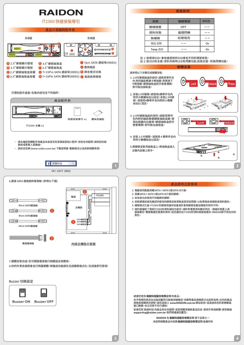
Raidon iT2300 Quick installation guide

National Instruments
National Instruments PXI-8186 user manual