3Com 3644A User manual


3600 Series Programmable Power Supply
VERSION 2.0 2004.6
26
3600 SERIES USER MANUAL
Safety Guide...............................................1
Attention......................................................2
Chapter 1 General Introduction ...................4
1.1 General Introduction...............................4
1.2 Specifications.........................................4
1.3 Features ..............................................5
1.4 Dimensions and Structure.......................5
1.4.1 Dimension...........................................5
1.4.2 Structure.............................................6
1.4.2.1 Front view .......................................6
1.4.2.2 Back view........................................7
Chapter 2 Operation....................................8
2.1 General operation .................................8
2.2 Function introduction..............................8
2.2.1. Main functions..................................8
2.2.2 Sub-functions.....................................8
CONTENTS
Programmable DC
Power supply
3600 SERIES
user’s manual
2.3 The operation of the function...................8
2.3.1 Set up voltage..................................9
2.3.2 Set up current...................................10
2.3.3 Enable/disable the output....................10
2.3.4 Store parameters..............................11
2.3.5 Recall parameters.............................12
2.3.6 The function of the Menu...................12
2.3.6.1 Set up the maximum
output voltage..............................13
2.3.6.2 Set up the maximum
output power .............................13
2.3.6.3 Enable/disable the rotary knob..........14
2.3.6.4 Set up the initial out state...............14
2.3.6.5 Save voltage setting.........................14
2.3.6.6 Set up communication speed...........14
2.3.6.7 Set up communication
address (0~31)..............................15
2.3.6.8 Lock the keypad...........................15
2.3.6.9 Clear saved parameters....................15
2.3.6.10 Exit ..............................................15
Chapter 3 Installation of PowerMS Software
...................................................16
3.1 System Installation...............................16
3.2 System Start.........................................17
3.3 System Uninstallation...........................18
Chapter 4 The Introduction of main functions
................................................19
4.1 The Definition of the Power Supply..........19
4.2 The COM Port andAddress Set.............20
4.3 Start the Communication........................21
4.4 Stop the Communication.......................21
4.5 Select POWER.....................................21
4.6 Select PC to POWER
Control Instructions..............................22
4.7 Set the Voltage Range..........................22
4.8 Set the Max Current..............................22
4.9 Query the Report..................................23
4.10 Explanation of the Interface
Indicating Components.......................24
4.11 The State Bar......................................24
4.12 Power Supply State Indication..............25
4.13 Exit the System..................................25

3600 Series Programmable Power Supply
VERSION 2.0 2004.6
3600 SERIES USER MANUAL
1
SAFETY GUIDE
This manual contains the precautions necessary to ensure your personal safety as well
as for protection for the products and the connected equipment. These precautions are
highlighted with a triangle “WARNING” symbol in this manual and are marked according to
the danger levels as follows:
Danger
It indicates that if appropriate precautions are not taken, serious incidents of personal
injuries and deaths or significant damages or losses to the properties will be caused.
Caution
It indicates that if appropriate precautions are not taken,injuries or losses of properties
will take place
Note:
Reminds you to pay particular attention to the important information related to the
products, disposal of products or the specific part of documents.
Warning
Only qualified personnel are allowed to debug and operate this equipment. The qualified
personnel are specified as those personnel who carry out commissioning, grounding and
apply the volume identification to the circuits, equipment and systems according to the
available safety practices and standards.
Note
Only when this product is transported, stored assembled and installed in a proper way
and operated and maintained according to the recommendations, can it implement the func-
tions properly and reliably.

3600 Series Programmable Power Supply
VERSION 2.0 2004.6
2
3600 SERIES USER MANUAL
The following general safety precautions must be observed during all phases of
operation, service, and repair of this instrument. Failure to comply with these precau-
tions or with specific warnings elsewhere in this manual violates safety standards of
design, manufacture, and intended use of the instrument. The Manufacturer assumes
no liability for the customer’s failure to comply with these requirements.
I.Safety
1. Users should operate according to this manual.
2. There is high voltage inside the instrument, please avoid touching it directly.
3. Please read the user manual carefully before you use the instrument to assure your
safety.
4. Ground the Instrument
This product is provided with a protective earth terminal. To minisize shock hazard,
the instrument chassis and cabinet must be connected to an electrical ground. The
instrument must be connected to the AC power supply mains through a three-conduc-
tor power cable, with the third wire firmly connected to an electrical ground (safety
ground) at the power outlet.
5.KeepAway From Live Circuits
Operating personnel must not remove instrument covers. Component replacement
and internal adjustments must be made by qualified service personnel. Do not split the
components when power cable connected.
Under certain conditions, dangerous voltages may exist even with the power cable
removed. To avoid injuries, always disconnect power, discharge circuits and remove
external voltage sources before touching components.
Do Not Substitute Parts or Modify Instrument
Because of the danger of introducing additional hazards, do not install substitute
parts or perform any unauthorized modification to the instrument. Return the instrument
to a qualified dealer for service and repair to ensure that safety features are maintained.
II.Connecting thepowerline
1. Inspect the power selection switch on the back panel, to assure if the selected
voltage is the same as environment power voltage. If not, please refer to the notice
around the power plug.
2. Before connecting the power supply, please be sure that the switch on the front
panel should be in the off position.
Attention

3600 Series Programmable Power Supply
VERSION 2.0 2004.6
3600 SERIES USER MANUAL
3
3. Connect the power cable to the AC in the power supply and the 3 connector plug.
Please be sure that the power supply is grounded.
4. Press the switch on the front panel to switch on the instrument and you can start
to use it.
III.Fuse
1. The fuse is at the position of power input part on the back panel, for the purpose
of avoiding failure brought by using wrong voltage. Please pay attention to the follow-
ing items when you change the voltage input and the fuse.
2. Before changing the voltage and fuse, please be sure that theAC power is switch-
ing off, and be sure that there is no other equipment connected to this instrument.
3. Put a screwdriver into the fuse mounting, press it and the fuse mounting will pop up.
4. Pull out the fuse, change it according to the label beside the power input plug.
Warning: To avoid damaging the instrument, please be sure to change a suitable
typefuse.
IV.Powersupply
1. For safety reasons, please be sure not to have any short circuit between plus and
minus pole.
2. Output wire should be insulated completely to the connected equipment.
3. Before using the instrument, you should switch on the power supply for 30 minutes.

3600 Series Programmable Power Supply
VERSION 2.0 2004.6
4
3600 SERIES USER MANUAL
Model 3644A 3645A 3646A
Number of outputs 1 1 1
DCoutputs
Voltage 0 to 18V 0 to 36V 0 to 72V
Current 5A 3A 1.5A
Power(max) 90W 108W 108W
LineRegulation
Voltage 0-3.999V: 0.01% + 3mV 0-3.999V: 0.01% + 3mV 0-3.999V: 0.01% + 3mV
4-18V: 0.02% + 10mV 4-36V: 0.02% + 10mV 4-72V: 0.02% + 10mV
Current 0.02% + 8mA 0.02% + 8mA 0.02% + 8mA
LoadRegulation
Voltage 0.02% + 20mV 0.02% + 10mV 0.02% + 10mV
Current 0.02% + 15mA 0.02% + 10mA 0.02% + 8mA
Rippleandnoise
Voltage <1mVrms <1mVrms <1mVrms
Current <5mArms <4mArms <3mArms
Programming accuracy
at 25 C+/- 5 C
Voltage 0.1% + 20mV 0.1% + 20mV 0.1% + 20mV
Current 0.2% + 20mA 0.2% + 20mA 0.2% + 20mA
Readbackaccuracy
at 25 C +/- 5 C
Voltage 0.2% + 20mV 0-19.999V: 0.2% + 20mV 0-19.999V: 0.2% + 20mV
20-36V: 0.2% + 100mV 20-72V: 0.2% + 100mV
Current 0.2% + 20mA 0.2% + 20mA 0.2% + 20mA
Program resolution
Voltage 0-3.999V: 1mV 0-3.999V: 1mV 0-3.999V: 1mV
4-18V: 10mV 4-36V: 10mV 4-72V: 10mV
Current 1mA 1mA 1mA
Readbackresolution
Voltage 10mV 0-19.999V: 10mV 0-19.999V: 10mV
20-36V: 100mV 20-72V: 100mV
Chapter 1 General Introduction
1.1 General Introduction
TheARRAY 3600 Series Power Supply is a compact programmable DC power supply. It is
equipped with back-light LCD display, number keypad and rotary knob which make it much
easier to use. It can be operated at constant voltage mode or constant current mode. Pro-
gramming feafures include over-current protection, maximum output voltage and power
limitation, and 10 parameters storage. It is an essential instrument for scientific research,
education, service and so on institutions.
1.2 Specification

3600 Series Programmable Power Supply
VERSION 2.0 2004.6
3600 SERIES USER MANUAL
5
1.3 Features
1. LCD display with back light.
2. Number keypad and rotary knob.
3. Maximum output voltage limitation.
4. Maximum output power limitation.
5. 10 parameters storage.
6. Can be series / parallel connected to expand output voltage/ current.
7. Free power management software.
1.4 Dimensions and Structure
1.4.1 Dimension
Fig 1 Dimension of 3600 Series Programmable DC power supply
Current 10mA 10mA 10mA
Protection Over voltage / Over current / Over power
ACInput 110V/220Vac +/- 15%, 47 to 63 Hz
Operatingenvironment
0 to 50 C, 80% RH *
Weight 6.00kg
Dimensions 212.6mmW x 88.1mmH x 250mmD
Software PowerMS Power Management System software,ActiveX and
DLL tools support VB, VC++, DELPHI, LABVIEW
StandardAccessories
User’s manual, AC cable, handlebars, software CD
OptionalAccessories
RS232 adaptor, RS485 adaptor, USB adaptor, Mounting rack
* 0 to 35 C for full rated output.At higher temperaturers, the output current is derated 3% per C.

3600 Series Programmable Power Supply
VERSION 2.0 2004.6
6
3600 SERIES USER MANUAL
0~9: The number keys
Store: Save the current setting value
Recall: Read the saved setting value
Menu: The menu operation key
OUT ON/OFF: Enable/disable the output
Enter: The confirmation key
V-set: The output voltage set
I-set: The max output current set
: The up moving key
: The down moving key
V/A: Set the voltage as V
Set the current as A
mV/ mA : Set the voltage as mV
Set the current as mA
The Left-upper Corner: The set voltage value.
(Flashing voltage means the low-voltage.)
The Left-bottom Corner: The output power value.
(Flashing power value means the over power.)
The Right-upper Corner: The output current value.
The Right-bottom Corner: The state value.
In common state, the keypad will execute
the prompting functions of the black words.
And in special mode, it will change into the
functions of the blue color words.
1.4.2 Structure
1.4.2.1 Front view
Front panel is for users to operate.
Please see the right picture for details.
1. LCD Display
2. Number Keypad
3. Rotary knob
4. Output Terminal Fig 2 Front view of 3600 Series DC power supply
1. LCD display
2. Arrangement of the Keyboard
Fig 4 Key board of 3600 Series DC
power supply
ON(OFF):
represents the output state of the power supply .
PC:
represents the operation is controlled by the computer.
0.00V 0.00A
0.00W OFF
Fig 3 LCD Display of 3600 Series
powersupply

3600 Series Programmable Power Supply
VERSION 2.0 2004.6
3600 SERIES USER MANUAL
7
3. Rotary knob and function keys
Left Operation: The left moving key
Right Operation: The right moving key
ESC: Can be used to exit from any working state
OK: Confirmation key
Rotary knob: The rotary dial
Fig 5 Rotary knob and function keys
1.4.2.2 Back view
Fig 6 Back view
The fuse can be changed easily by using a small screwdriver.
fan wrap
AC input switch
PC connection
interface
Power supply plug
Wire rack
Fuse

3600 Series Programmable Power Supply
VERSION 2.0 2004.6
8
3600 SERIES USER MANUAL
Chapter 2 Operation
2.1General operation
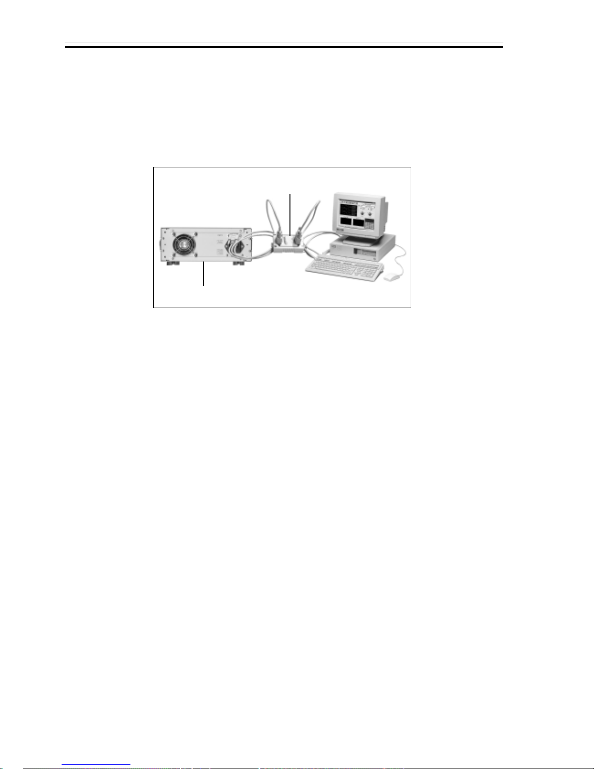
1. Connect the power supply with PC
2.2Functionintroduction
2.2.1. Main functions
1. Set up voltage
2. Set up current
3. Enable/disable the output
4. Store parameters
5. Recall parameters
2.2.2 Sub-functions
1. Set up the maximum output voltage
2. Set up the maximum output power
3. Enable/disable the rotary knob
4. Set up initial output state
5. Save voltage setting
6. Set up the communication speed
7. Set up the communication address
8. Lock the keypad
9. Clear saved parameters
2.3Theoperation ofthe function
There are 5 main functions and 9 sub-functions of this power supply, please refer to the
operation of these functions as follows:
Fig 2-1Connectthepowersupply withPC
3600 Series power supply
3311 adaptor
This manual suits for next models
3
Table of contents
Other 3Com Power Supply manuals