2T Technology Voyager Voice Sleek Instruction Manual

Voyager Voice - Sleek Model
2G & 3G Intercom system
Installation & User Manual
Scan the QR code and
watch the installation video.

2
Contents
Before Installation .................................................................................... 3
Pillar or Wall Mounting the Intercom ...................................................... 4
Wiring of the Intercom ............................................................................. 5
Powering Up............................................................................................. 6
Getting The Intercom Setup App.............................................................. 9
Starting with The App ........................................................................ 10
Setting Call In and Call Out Phone Numbers..................................... 11
Using The Intercom............................................................................ 12
Out Of Hours Setup (Do Not Disturb)................................................ 13
Keypad Codes..................................................................................... 14
Automatic Schedules.......................................................................... 15
Configure Input 1 and Input 2 for Open & Close Status........................ 16
Set Ring and Talk Time for Outgoing Calls........................................... 17
Force the Intercom to Operate on 3G only............................................. 17
Options for Security Settings.................................................................. 18
Program the Control Phone. ................................................................... 18
Diagnostics ............................................................................................. 19
RED LED - System Health Status Indicator .......................................... 21
Trouble Shooting Guide ......................................................................... 22
3
Before Installation
This system should only be installed by a professional automatic gate installer
or access control specialist.
Please ensure you are familiar with the function and features of this system by
using the system on a workshop bench before you go to site for installation.
Site Signal Level Survey
Please check the signal levels for the network you are about to use to
install this system. Some GSM networks have good coverage in some areas and
none in other areas.
Once installed the device will display the signal level it sees on the
Signal Strength LED on the PCB and will respond to an SMS text command to
give the Signal Level it is receiving from the network you are using. Please
confirm this level is good. SIM Card
If there is no SIM installed then you will have to:
A) Obtain a SIM with credit. This device is a 2G/3G device so all available
SIM cards should work without a problem.
B) When obtaining the SIM ask that voice mail is turned off.
C) Vodafone and O2 PAYG SIM cards don’t have a PIN number on the SIM.
But other operators still put a security PIN on their SIM cards. This must
be removed before using the SIM on the GSM device.
Note:
Some functions of this GSM device, like Keypad Codes, are
dependent on the GSM device having the correct date and time
of day. The GSM device gets this by sending itself an SMS
text after power up. To do this the SIM must have credit and
without this, many of the features of Keypad Codes will be
absent or fail to operate.
For this and other reasons we strongly recommend the use of a
Bill Pay contract SIM with this intercom. Please contact your
on our cost competitive Bill Pay SIM.
4
Power
A) Please use the power supply provided with the device
B) Please place the power supply within a meter or two of the device.
Long runs of narrow cable will cause problems.
C) For longer runs of power cable between the power supply and the
device
Up to 2 meters - Use minimum 0.5mm2 (20 gauge)
Up to 4 meters - Use minimum 0.75mm2 (18 gauge)
Up to 8 meters - Use minimum 1.0mm2 (16 gauge)
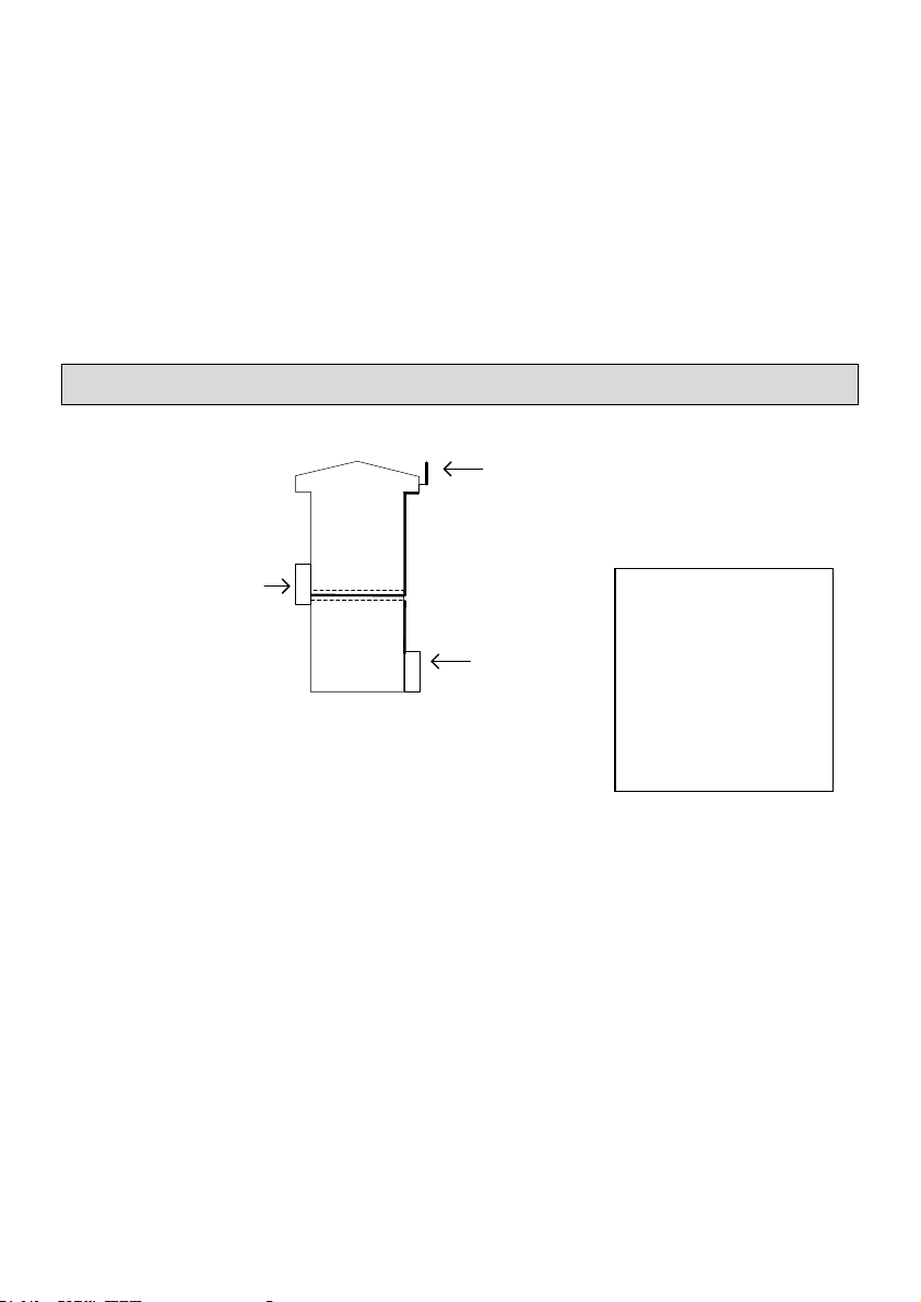
Pillar or Wall Mounting the Intercom
Pillar or wall
Mounting
Intercom
Power unit
in box
Antenna
Mounted above the height
of the wall or pillar
1. Unscrew the top two screws from the body of the intercom.
There are four security screws holding the front panel to the body of the
intercom. The tool for opening these screws is in the box. Please leave
the plastic protection on the Intercom body until your installation is
complete to protect the surface from scratches.
2. Use the body (rear part) of the intercom to mark the wall or
pillar for mounting the intercom. There are four screw holes for
mounting the intercom to the wall.
3. Decide how to run the power supply cable and the antenna
cable, as these must enter the intercom through the biggest hole in the
back of the Intercom body.
4. Mount the intercom to the wall.
**Keep the Antenna
at least 1 meter from
the Intercom and at
least 1 meter from
the Power unit. Keep
the power unit at
least 0.5 meter from
the Intercom.
5
5. Now wire the Power Supply and relay output to the terminals
on the PCB as described in the diagrams that follow.
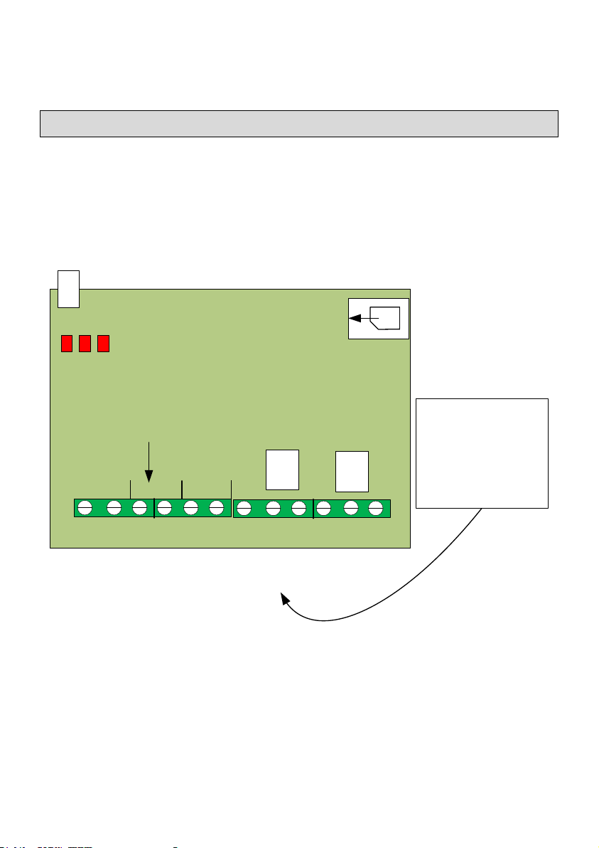
Wiring of the Intercom
Overview of the main GSM PCB
The Diagram below shows the key connection points on the GSM
Intercom PCB.
Relay 2
- + 1 2 NO COM NC
2
INPUTS
Output 2Output 1
Output 1
Gate or Door
Control when
using
Open Access
Relay 1
NO COM NC
P N
DC 12V
Power In
Power to
Side
Light
PCBs
Micro
SIM
Holder
Antenna
DC 12V
Power In

6
Wiring to the PCB
1. Output connection example
Relay 2
NO COM NC
Output 2
Output 1
Relay 1
NO COM NC
Gate
Controller
Keypad or
Push button
Exit device
Magnetic
Lock
Keypad or
Push Button
Exit Device
12V DC
Separate PSU
Main PCB
Powering Up
1. Insert the SIM in the GSM device.
A Micro SIM card for a
mobile phone is required.
The SIM card may be
labelled 3G/4G/5G.
Do not use a SIM card for
a tablet or a data only
SIM.
SIM Card
Holder SIM
Insert
This Way.
Main
PCB

7
2. Apply power to the GSM unit.
The device will ask you to wait.
Initially the Register light will be on constant and as the unit registers on
the network, will start to flash every 1 second.
3. Give the Unit about 2 minutes to register when first turned on.
When the Signal Strength light is on constantly or flashing the unit has
signal from the network. If the signal strength light fails to light at all
you may have to change the position of the device to pick up a GSM
signal. Raise the antenna to the highest position possible. It may also be
an option to use a SIM from a different network. On some occasions it
may be necessary to use a high gain antenna, please contact your supplier
for this.
Signal Strength
Power Network Register
Status
Antenna
Mobile Network Signal Strength.
1. On Steady: Strong Signal
2. Flashing: Acceptable Signal.
3. Off: No Signal.
Network Register Status.
1. Off or On Constantly =
NOT Registered
2. Flashing every second =
Registered.
4. Wait for Beep-Beep
After between 30 and 60 seconds you will hear the GSM unit go Beep-
Beep.
After you hear Beep-Beep the unit is ready for programming and
operation.
5. Program the units own phone number into the device.
For the operation of the Keypad, Timers (scheduled events) and the Log
the unit needs to know the correct time of day. It gets this from received
SMS Text messages.

8
So that the unit can send itself a text message to synchronise the time of
day it needs to know its own phone number.
A) Get the telephone number from the SIM card that you have taken
the SIM for the unit from.
B) Program this into the GSM device as follows.
Send this text. Receive This Text Response
SIM set xxxxxxxxx SIM Phone number
xxxxxxxxx Programmed.
*xxxxxxx represents the GSM device’s mobile number eg:0872376605
6. Check Reception levels
Initial installation is now complete. Use the SMS text command below to
confirm signal level is acceptable for the GSM device.
Send this text. Receive This Text Response
Diag Levels See table for response
explanation
Example Response
Meaning
VV-IKL
VV-IKL = Voyager Voice Integrated Keypad
with LEDs
57
SW version 5.7
Signal Level XX
The Current Signal Level
For 2G operation:
this number needs to be 10 or higher.
For 3G Operation:
this number needs to be 8 or higher.
Mode is XG
Current mode of operation
2G = 2G Mode 3G = 3G Mode
SIM Number
This is the GSM device’s own phone number.
( Set with the “SIM set xxxxx” command )

9
Please Note: Having set the SIM number in the device at step 5. In the
last section, the device can now send itself an SMS text on powering up
to synchronise its internal clock. This will be heard as a second Beep-
Beep when this text is received by the GSM device. When powering up
the device please wait until after both sets of Beep-Beep occur before
proceeding to use or configure the GSM device.
Getting The Intercom Setup App
For a download link, for the App,
1) go to our website at
http://2t-tec.com/download/
2) On this page go to the heading "Engineer Setup Apps" and then
look for "Voyager Voice Intercom"
The App contains the majority of setting options for use with the
Intercom. Some additional options, where you must send text to the
device, are covered at the end of this manual.
Please use this manual in conjunction with the phone App.
10
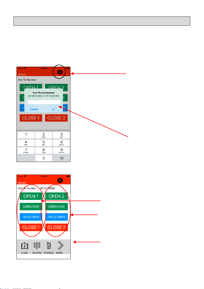
Starting with The App
This section covers some of the main points of interest when using the
Phone App for programming the GSM Intercom. We will cover five
sections here which should give an overview of what can be done, but
there are many other items that can be configured with the Phone App.
First Screen
If you need to change
the Phone number that the App is
communicating with. Or if this GSM Intercom
has a security code enabled. Then configure
these settings by pressing the configuration
wheel. (** Please note to enable the Security
code requires sending an SMS text. See page
18. Setting it as Enabled in the App just tells the
App that the Security code is on, in this device.)
Enter the Phone
Number for the GSM Intercom at this site. Then
press ok.
Once the Phone number is entered this first
screen can be used for immediate control of the
two Outputs.
Control Output 1
Control Output 2
Select other screens in the App
to configure Keypad codes, Phone Numbers
and other items.
Table of contents
Other 2T Technology Intercom System manuals


