Weinmann VENTIremote WM 27745 Operating and installation instructions
VENTIremote alarm
Remote alarm case
VENTIremote alarm 10 m WM 27745
VENTIremote alarm 30 m WM 27755
Device description and instructions for use
2Overview
EN
Overview
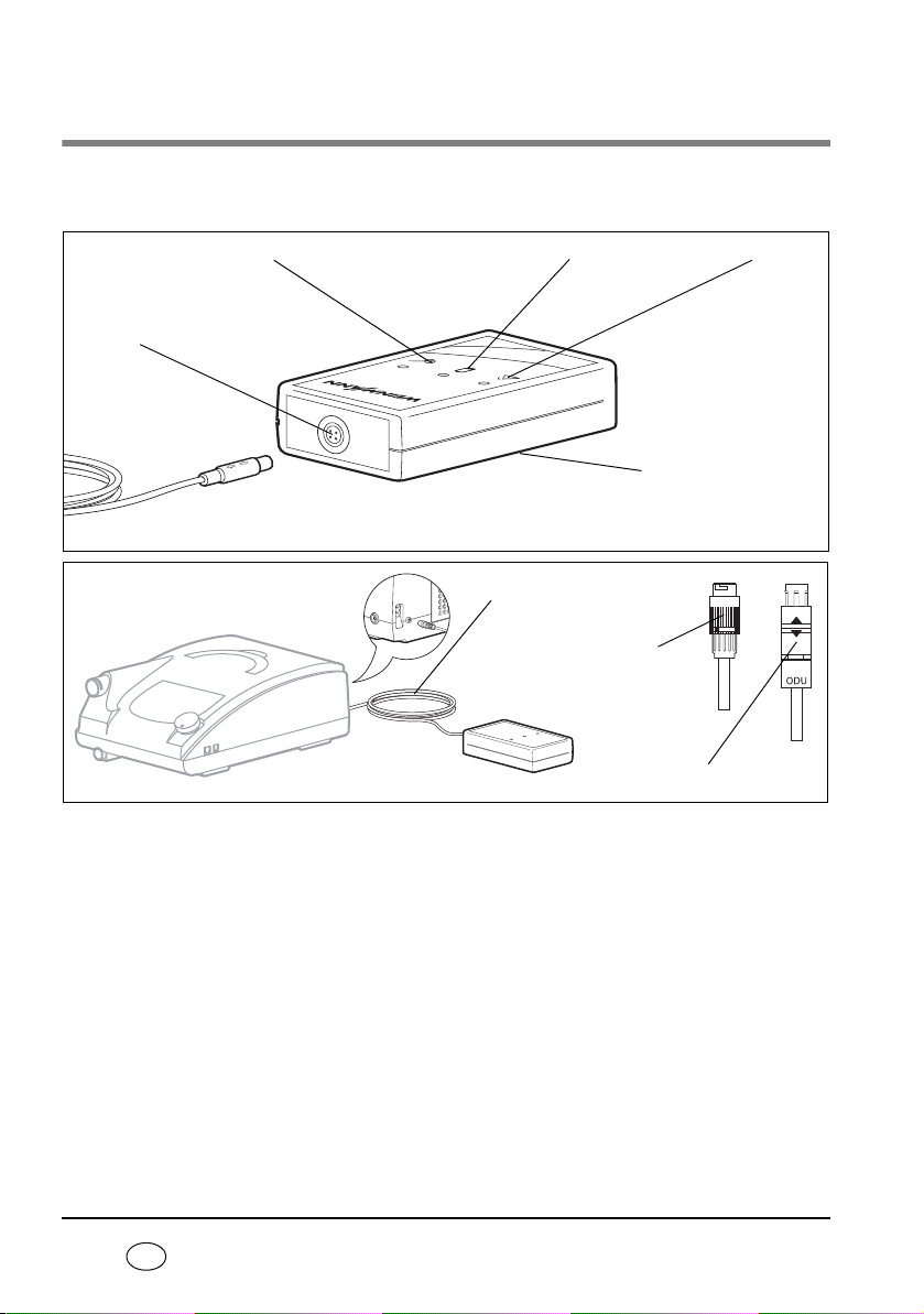
Key
1Battery indicator
If this yellow LED flashes, the battery needs chang-
ing.
2Alarm indicator
In combination with the buzzer, this red LED indi-
cates an alarm of the therapy device or a malfunc-
tion of the VENTIremote alarm.
3Nameplate
Provides information about the device, such as se-
rial number and year of manufacture, for exam-
ple.
4ODU socket
This is where the ODU connector (two white ar-
rows) for the connecting cable to the
VENTIremote alarm is connected.
5Stand-by indicator
This green LED indicates that the VENTIremote
alarm is working correctly.
6Connecting cable
This connecting cable passes alarms from the ther-
apy device to the VENTIremote alarm.
VENTIremote alarm
4ODU socket
5Stand-by indicator 1Battery indicator 2Alarm indicator
3Nameplate
6Connecting cable
7Bayonet
connector
8ODU connector
Special markings on the device 3
EN
7Bayonet connector
This connects the connecting cable to the therapy
device.
8ODU connector
This connects the connecting cable to the
VENTIremote alarm.
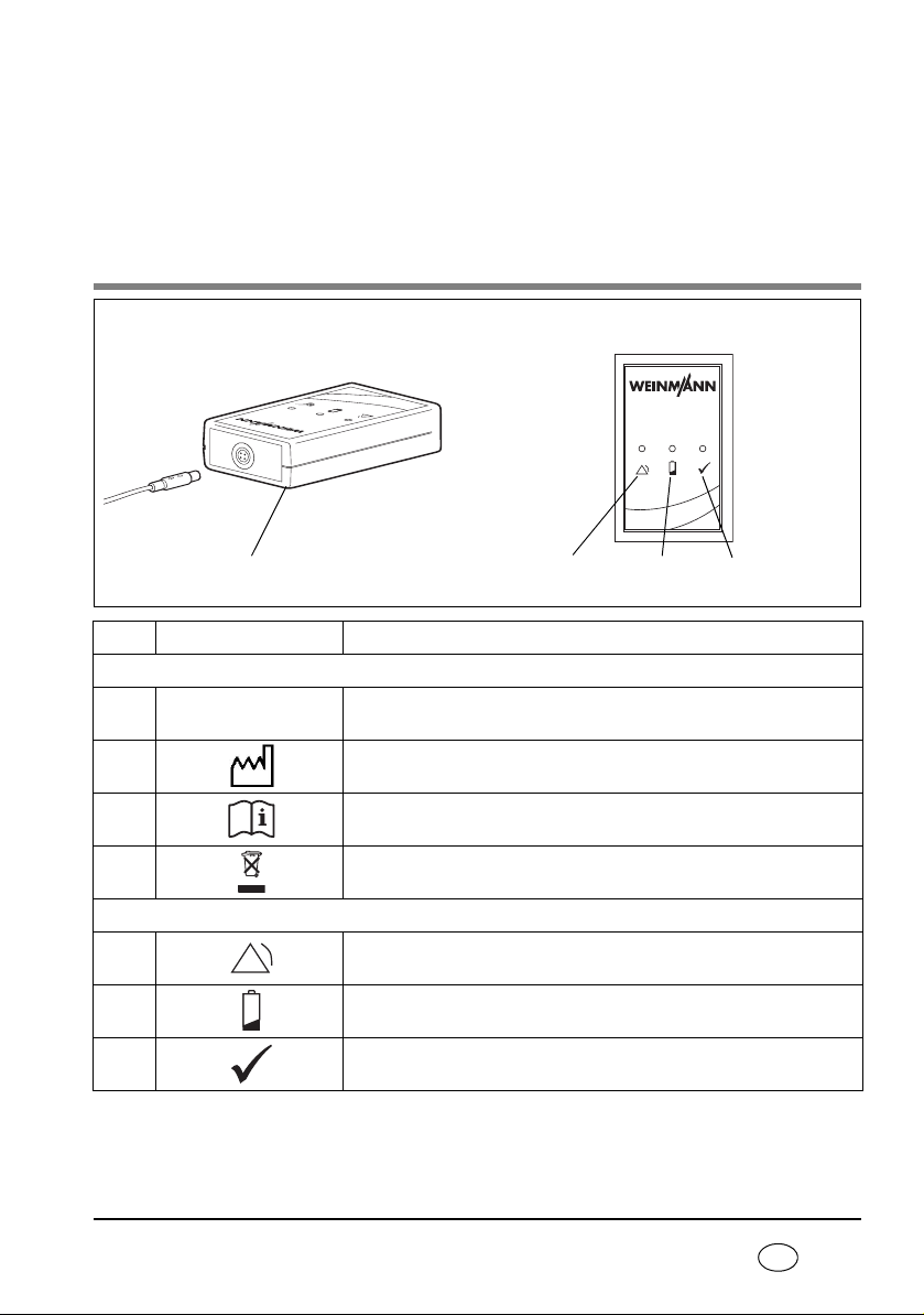
Special markings on the device
Symbols Significance
Name plate
Serial number
Year of manufacture
Follow information in the instructions for use
Do not dispose of device in domestic waste
Display fascia
1Red LED illuminated: alarm
2Yellow LED flashing every six seconds: battery almost dead
3Stand-by indicator: the green LED must light briefly every six seconds
during operation
VENTIremote alarm
VENTI
remote alarm
123Name plate
SN

4Safety information in these instructions
EN
Safety information in these
instructions
Safety information in these instructions for use is marked as follows:
Warning!
Warns of risk of injury and potential material damage.
Caution!
Warns of material damage and potentially false therapy results.
Note:
Contains useful tips.

Contents 5
EN
Contents
1. Description of device . . . . . . . . . . 6
1.1 Intended use. . . . . . . . . . . . . . . . . 6
1.2 Description of function . . . . . . . . 6
2. Safety instructions . . . . . . . . . . . . 7
3. Set up and operate the device . . 9
3.1 Initial commissioning . . . . . . . . . . 9
3.2 Set up and connect the device . . 10
3.3 Operation with the therapy device 11
3.4 Change battery. . . . . . . . . . . . . . 11
4. Hygienic preparation . . . . . . . . . 13
4.1 Cleaning. . . . . . . . . . . . . . . . . . . 13
4.2 Disinfecting . . . . . . . . . . . . . . . . 13
4.3 Sterilizing . . . . . . . . . . . . . . . . . . 13
4.4 Change of patient . . . . . . . . . . . 13
5. Function check . . . . . . . . . . . . . . 14
5.1 Intervals . . . . . . . . . . . . . . . . . . . 14
5.2 Performing the function check . . 15
6. Troubleshooting . . . . . . . . . . . . . 17
7. Servicing . . . . . . . . . . . . . . . . . . . 18
7.1 Storage. . . . . . . . . . . . . . . . . . . . 18
7.2 Disposal . . . . . . . . . . . . . . . . . . . 18
8. Scope of supply . . . . . . . . . . . . . 19
8.1 Standard scope of supply . . . . . . 19
8.2 Accessories and spare parts . . . . 19
9. Technical data . . . . . . . . . . . . . . . 20
9.1 Specifications . . . . . . . . . . . . . . . 20
9.2 Safety distances . . . . . . . . . . . . . 21
10. Warranty . . . . . . . . . . . . . . . . . . . 22
11. Declaration of conformity . . . . . 23
12. Index . . . . . . . . . . . . . . . . . . . . . . 24

6Description of device
EN
1. Description of device
1.1 Intended use
VENTIremote alarm is for the remote transmission and display of acoustic and visual alarm
signals issued by the VENTIlogic LS and VENTIlogic plus therapy devices. With VENTIremote
alarm, alarms relating to respiratory physiology and device faults can be remotely moni-
tored independent of any nurse-call system which may be installed.
VENTIremote alarm helps in particular nursing staff and family members when caring for a
ventilated patient in the home environment. VENTIremote alarm can only be operated in
conjunction with the Weinmann VENTIlogic LS and VENTIlogic plus ventilation devices.
1.2 Description of function
VENTIremote alarm has a connecting cable (10 m and 30 m long) to connect it to the ther-
apy device. If the therapy device issues alarms, the VENTIremote alarm converts these into
visual and acoustic signals and outputs them. The device is powered by a 9 V battery pack
(lithium).
Safety instructions 7
EN
2. Safety instructions
Read these instructions for use carefully. They are an integral part of the device and must
be available at all times. Only use the device for the intended purpose described (see “1.1
Intended use” on page 6).
For your own safety and the safety of your patients and in accordance with the require-
ments of Directive 93/42/EEC, please note the following:
Operating the device
Warning!
• Ensure that the VENTIremote alarm is free-standing and not covered up,
otherwise alarm volume is reduced. This can lead to a risk to the patient and to
damage to the device.
• Maintain a safe distance between the VENTIremote alarm and equipment that
emits HF radiation (e.g. cell phones), otherwise there may be malfunctions.
Caution!
• To prevent infection or bacterial contamination, observe section “4. Hygienic
preparation” on page 13.
• Ensure that the connecting cable is correctly connected to prevent the connector
being pulled out inadvertently and to ensure that the VENTIremote alarm works
correctly.
Note:
Always keep a full U9VL-BP-type battery to hand.
Transport/Replacement parts/Maintenance/Storage
Caution!
• If the VENTIremote alarm has been stored or transported outside the operating
temperatures quoted in the instructions for use, the VENTIremote alarm should
be commissioned only once the temperature of the device is within the
permitted range for operation.

8Safety instructions
EN
• If third-party items are used, functional failures may occur and fitness for use
may be restricted. Biocompatibility requirements may also not be met. Please
note that in such cases, any claim under warranty and liability will be voided if
neither the accessories nor genuine replacement parts recommended in the
instructions for use are used.
• Have servicing and maintenance work carried out only by the manufacturer,
Weinmann, or by specialists expressly authorized to do so by the manufacturer.
• Have modifications to the device carried out only by the manufacturer,
Weinmann, or by specialists expressly authorized to do so by the manufacturer.
Note:
• Remove the battery if the VENTIremote alarm is in storage or not being used for
an extended period.
• In the event of questions about faults, see the section entitled “6.
Troubleshooting” on page 17.
Set up and operate the device 9
EN
3. Set up and operate the device
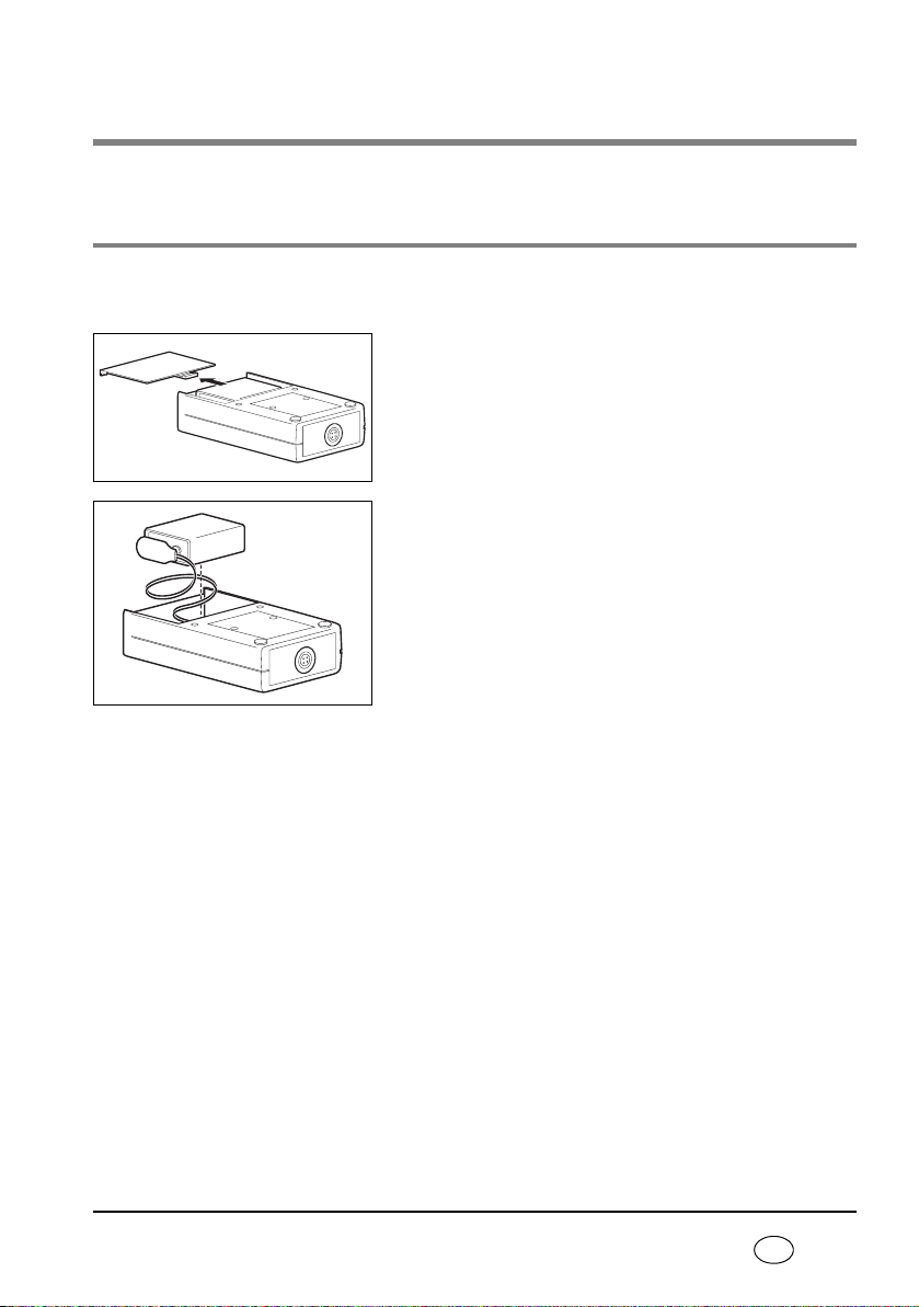
3.1 Initial commissioning
Before you can operate the VENTIremote alarm as described below, you have to insert the
U9VL-BP-type battery included in the scope of supply. To do so, proceed as follows.
1. Open the battery compartment as shown in the adja-
cent drawing.
2. Connect the battery to the connecting cables.
3. Put the battery and the connecting cables in the bat-
tery compartment.
Note:
Ensure that the connecting cables are underneath
the battery in the battery compartment, so that
the connecting cables are not trapped when the
battery compartment is closed.
4. Push the battery compartment cover closed until it
engages with an audible click.
VENTIremote alarm is now ready for operation.
10 Set up and operate the device
EN
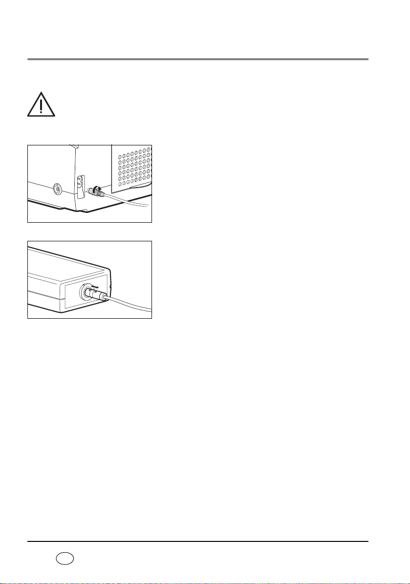
3.2 Set up and connect the device
1. Place the VENTIremote alarm on a level surface.
Warning!
Ensure that the VENTIremote alarm is free-standing and not covered, otherwise
alarm volume will be reduced. This can lead to a risk to the patient and to damage
to the device.
2. Connect the bayonet connector of the connecting ca-
ble to the remote alarm connection of the therapy
device.
3. Connect the ODU connector (two white arrows) of
the connecting cable to the ODU socket of the
VENTIremote alarm. To do so, turn the ODU connec-
tor so that the arrows on it and the arrow on the
ODU socket are pointing at one another.
As soon as the ODU connector is connected to the
VENTIremote alarm, the VENTIremote alarm automatical-
ly performs a function check.
Note:
Ensure that the connector engages correctly in
the socket.
This manual suits for next models
1
Table of contents
Popular Security System manuals by other brands


EDM
EDM Solution 6+6 Wireless-AE installation manual

Highway Safety Group
Highway Safety Group EA401 user manual

Siren
Siren LED GSM operating manual

Detection Systems
Detection Systems 7090i Installation and programming manual

Se-Kure Controls
Se-Kure Controls MicroMini SK-4841 instructions

Siemens
Siemens FDM273 manual