Sony PDJ-A640 User manual

PROFESSIONAL DISC CART
PDJ-A640
INSTALLATION MANUAL
1st Edition (Revised 2)
Serial No. 10001 and Higher
PROFESSIONAL DISC CART MOUNT KIT
PDBK-A640
PDJ-A640 IM
!WARNING
This manual is intended for qualified service personnel only.
To reduce the risk of electric shock, fire or injury, do not perform any servicing other than that
contained in the operating instructions unless you are qualified to do so. Refer all servicing to
qualified service personnel.
!WARNUNG
Die Anleitung ist nur für qualifiziertes Fachpersonal bestimmt.
Alle Wartungsarbeiten dürfen nur von qualifiziertem Fachpersonal ausgeführt werden. Um die
Gefahr eines elektrischen Schlages, Feuergefahr und Verletzungen zu vermeiden, sind bei
Wartungsarbeiten strikt die Angaben in der Anleitung zu befolgen. Andere als die angegeben
Wartungsarbeiten dürfen nur von Personen ausgeführt werden, die eine spezielle Befähigung
dazu besitzen.
!AVERTISSEMENT
Ce manual est destiné uniquement aux personnes compétentes en charge de l'entretien. Afin de
réduire les risques de décharge électrique, d'incendie ou de blessure n'effectuer que les
réparations indiquées dans le mode d'emploi à moins d'être qualifié pour en effectuer d'autres.
Pour toute réparation faire appel à une personne compétente uniquement.
For safety, do not connect the connector for peripheral
device wiring that might have excessive voltage to the
following port(s).
: NETWORK connector
Follow the instructions for the above port(s).

1 (E)
PDJ-A640 IM
Table of Contents
Manual Structure
Purpose of this manual ........................................................... 3 (E)
Related manuals ..................................................................... 3 (E)
Major features ......................................................................... 3 (E)
Contents .................................................................................. 5 (E)
Trademarks ............................................................................. 5 (E)
1. Unpacking and Packing
1-1. Unpacking and Packing of PDJ-A640 ..................... 1-1 (E)
2. Installation Condition
2-1. External Dimensions and Mass ............................... 2-1 (E)
2-1-1. External Dimensions ...................................... 2-1 (E)
2-1-2. Mass ............................................................... 2-1 (E)
2-2. Precautions on Transportation ................................. 2-1 (E)
2-2-1. Moving the Main Unit on its Castors ............. 2-1 (E)
2-2-2. Moving the Unit on a Forklift ........................ 2-2 (E)
2-3. Installation Condition .............................................. 2-2 (E)
2-3-1. Operating Environment .................................. 2-2 (E)
2-3-2. Prohibited Locations for Installation .............. 2-2 (E)
2-3-3. Door Dimension and Ceiling Height of
the Room to Install the PDJ-A640 ................. 2-3 (E)
2-3-4. Maintenance Space ......................................... 2-4 (E)
2-4. Power Supply ........................................................... 2-5 (E)
2-4-1. AC Power Supply ........................................... 2-5 (E)
2-4-2. Power Cord ..................................................... 2-5 (E)
3. Installation Procedure
3-1. Precaution ................................................................ 3-1 (E)
3-2. Preparation ............................................................... 3-1 (E)
3-2-1. Fixtures Required for Installation .................. 3-1 (E)
3-2-2. Opening and Closing the Door ....................... 3-2 (E)
3-3. Installation Flowchart .............................................. 3-2 (E)
3-4. Securing the Professional Disc Cart Main Unit ....... 3-3 (E)
3-5. Setting System Control Unit .................................... 3-4 (E)
3-6. Removing/Moving the Fixed Parts at Shipment ...... 3-6 (E)
3-6-1. Removing/Installing the Shipping
Plate A of the Counter Weight ....................... 3-6 (E)
3-6-2. Moving the Shipping Plate B on
the Elevator Block .......................................... 3-6 (E)
3-6-3. Installing the Shipping Plates A and B to
the Rear Panel ................................................. 3-7 (E)
3-6-4. Moving the Shipping Ring ............................. 3-7 (E)
3-6-5. Removing/Installing the Bin Drum
Fixing Screws ................................................. 3-8 (E)
3-6-6. Cautions When Transporting the Cart
Machine .......................................................... 3-8 (E)
3-7. Installing the DECK ................................................ 3-9 (E)
3-8. Setting the Barcode Type ....................................... 3-14 (E)
3-9. Connecting/Tying the Cables ................................ 3-17 (E)
3-9-1. Basic Cable Connections .............................. 3-17 (E)
3-9-2. Procedure of Connecting the Power
Cable and Turning On the Power ................. 3-19 (E)
3-9-3. Tying the Cables ........................................... 3-19 (E)
3-10. Setting the DECK .................................................. 3-20 (E)
3-11. Setting the DECK Mounted on the PDJ-A640 ...... 3-20 (E)
3-11-1. SNo.10001 to 10008 ..................................... 3-20 (E)
3-11-2. SNo.10009 or higher .................................... 3-26 (E)
3-12. Inserting/Removing the Optical Disc Cartridge .... 3-27 (E)
3-13. Optimization of the Bin Position ........................... 3-28 (E)
4. Input/Output Interface
4-1. Connecting Connectors and Cables ......................... 4-1 (E)
4-2. Input and Output Signals of Connectors .................. 4-2 (E)
5. Installation and Settings when Connecting
the PDJ-CS10 (CART IF) to the CART
5-1. Setting the System Frequency
(NTSC DF/NDF and PAL)
Setting the Interface (RS-422A and RS-232C) ....... 5-1 (E)
5-1-1. Removing the Board Cover of the System
Control Board (Node Board) .......................... 5-1 (E)
5-1-2. Setting the DIP Switches (S4 and S8) on
the System Control Board (Node Board) ....... 5-2 (E)

2 (E) PDJ-A640 IM
5-2. Setting the Barcode Type ......................................... 5-2 (E)
5-3. Connecting the Disc Cart and the Cart Interface
(PDJ-CS10) .............................................................. 5-4 (E)
5-4. Connecting the Other Cables of the Disc Cart ......... 5-5 (E)
5-5. Setting the DECK Mounted on Cart ........................ 5-7 (E)
5-6. Version Check and Setting of Cart ........................ 5-10 (E)
5-7. PDW-F1600 Device Type Registration ................. 5-11 (E)
5-8. Optimization of the Bin Position ........................... 5-15 (E)
5-9. Check after Installing the PDJ-CS10 ..................... 5-16 (E)
5-10. Setup and Setting List ............................................ 5-18 (E)
6. SNMP
6-1. SNMP Installation Specifications and System
Configuration ........................................................... 6-1 (E)
6-1-1. SNMP Installation Specifications .................. 6-1 (E)
6-1-2. Default Community Settings When
Shipped from the Factory ............................... 6-1 (E)
6-2. Network Settings ..................................................... 6-2 (E)
6-3. How to Log On via Telnet ....................................... 6-3 (E)
6-4. SNMP Mode Command Details .............................. 6-4 (E)
6-4-1. SNMP Command List .................................... 6-4 (E)
6-4-2. Setconf Command .......................................... 6-5 (E)
6-4-3. Prconf Command ............................................ 6-6 (E)
6-4-4. Setmib Command ........................................... 6-7 (E)
6-4-5. Prmib Command ............................................ 6-8 (E)
6-4-6. Loadmib Command ........................................ 6-8 (E)
6-4-7. Storemib Command ........................................ 6-9 (E)
6-4-8. Quit Command ............................................... 6-9 (E)

3 (E)
PDJ-A640 IM
Purpose of this manual
This manual is the installation manual of Professional Disc Cart PDJ-A640.
This manual is intended for use by trained system and service engineers, and
describes the information on installing the PDJ-A640.
Related manuals
Besides this Installation Manual, the following manuals are prepared for PDJ-A640.
..
..
.Operation Manual (Supplied with PDJ-A640)
This manual introduces the Professional Disc Cart PDJ-A640 and its handling
methods, and explains the message information displayed on the screen.
This manual is required for running and operating the PDJ-A640.
..
..
.Maintenance Manual (Available on request)
This manual contains information on the servicing of the PDJ-A640 to the extent
of the assembly level (adjustments, block diagrams, parts list and so on). The
maintenance and inspection methods of the Professional Disc Cart PDJ-A640 are
described.
For obtaining, contact your local Sony Sales Office/Service Center.
Major features
The PDJ-A640 Professional Disc Cart is an automatic changer system for optical
disc cartridges in which 4 video decks (Professional Disc Recorders) and 640 optical
disc cartridges can be mounted at maximum.
You can record and store valuable materials of approx. 500 to 2000 hours (when
using the dual-layer discs) on optical discs of high durability and high accessibility
in the MXF (Material eXchange Format) format.
For control interface, the Cart employs RS-232C/422A and enables you to control it
using the conventional VCC protocol. In combination with upper-level application
software, the Cart can establish a system for auto-injest, archiving, and tape digitiz-
ing applications.
It accepts the PDW-1500 (SD model), the PDW-F70/F75*1(HD 4:2:0 model), the
PDW-HD1500*2and PDW-F1600 (HD 4:2:2/4:2:0 and SD model) in its video deck
shelf, enabling SD and HD combined operations.
*1: To install the PDW-F70/F75 in this Cart, the optional PDBK-A640 is required and for the PDW-F75, the
optional PDBK-104 is also required. For installation, refer to the Installation Manual supplied with the
PDBK-A640/PDBK-104.
*2: To make the PDW-HD1500 support both HD and SD, the PDBK-S1500 or PDBK-F1500 (sold separately)
is necessary. For details about the installation, refer to the installation guide supplied with the PDBK-
S1500 or PDBK-F1500.
Manual Structure

4 (E) PDJ-A640 IM
Highly reliable data recording/playback with multiple video decks in a
compact space
Up to 640 optical disc cartridges (PFD23/dual-layer PFD50DLA*3) can be stored in
a Cart of 680 mm in width. The Cart permits recording and playback in synchroniza-
tion with video frames using the mounted four (at maximum) Professional Disc
Recorders (PDW-1500/PDW-HD1500/PDW-F1600, or PDW-F70/PDW-F75 on
which the PDBK-A640 has been attached).
At the sametime, the Cart can read and written the MXF file via network using the
Cart Interface Software PDJ-CS10.
*3 : PFD50DLA supports PDW-HD1500, PDW-F1600 and PDW-F75.
Refer to the Operation Manual or Instruction Manual of the respective Disc Recorders for details.
Control with the conventional VCC protocol
The Professional Disc Cart conforms to the VCC interface (RS-232C/422A).
Operations with the conventional barcode system
A barcode reader is built into the elevator, and operations with the barcode system
are enabled with optical disc cartridges.
For details on the barcodes to be used with this product, see “Specifications” on the
Operation Manual.
Maintenance with SNMP
The Cart supports SNMP (Simple Network Management Protocol). For example,
monitoring using the Sony “MMStation” Remote Maintenance and Monitoring
Software is possible. This program enables you to monitor and record the hardware
statuses in real time via a TCP/IP network. If any hardware problem is detected, you
can analyse the problem at once and take necessary countermeasures.

5 (E)
PDJ-A640 IM
Contents
The following is a summary of all the sections of this manual.
Section 1 Unpacking and Packing
This section describes the package of the PDJ-A640 and the accessories.
Section 2 Installation Condition
This section describes the precautions on the operating environment of the PDJ-
A640 and on the installing location. The section also describes how to move the
PDJ-A640, and the space required for maintenance.
Section 3 Installation Procedure
This section describes how to secure the PDJ-A640 to the floor and the ceiling, and
how to set the system control unit. The section also describes the installation of the
PDW-1500/PDW-HD1500/PDW-F1600/PDW-F70/PDW-F75, cable connection at
the rear side, how to turn on the power, and how to handle the optical disc unit.
Section 4 Input/Output Interface
This section describes the information regarding the connection on the system
controller block of the PDJ-A640 (connecting connectors and cables, and input/
output signal of the connectors).
Section 5 Installation and Setting When Connecting the PDJ-CS10
(CART IF) to the CART
This section describes the necessary procedures for installation and setup when
connecting the PDJ-CS10 (CART IF) to PDJ-A640.
Section 6 SNMP
This section describes SNMP (Simple Network Management Protocol).
Trademarks
Trademarks and registered trademarks used in this manual are follows.
.Ethernet is a registered trademark of Xerox Corporation.
.XDCAM, Professional Disc and MMStation are trademarks of Sony Corporation.

1-1 (E)
PDJ-A640 IM
Section 1
Unpacking and Packing
1-1. Unpacking and Packing of PDJ-A640
.The PDJ-A640 can move on its castors.
c
At least three persons must work together for safety when bringing down the PDJ-A640 from the bottom
tray using the slope.
There maybe a height difference between the bottom tray and the slope, which catches the casters as the
PDJ-A640 passes over. Move the PDJ-A640 slowly and gently so that it does not tilt.
Operation Manual
Installation Manual
Eyebolt
Plug holder (C)
Blank panel A for PDW-F70
Blank panel B for PDW-F70
x1
x1
x4
x1
x4
x4
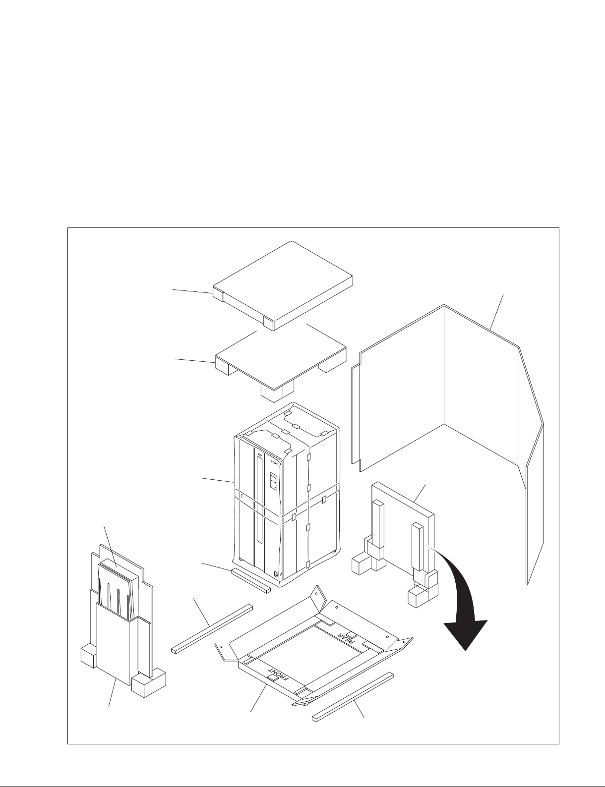
Accessories
Slope holder
Slope
Bottom tray Spacer
Spacer
Door support
Parts box
Panel
Top cap
Top pad
PDJ-A640
1-2 (E) PDJ-A640 IM
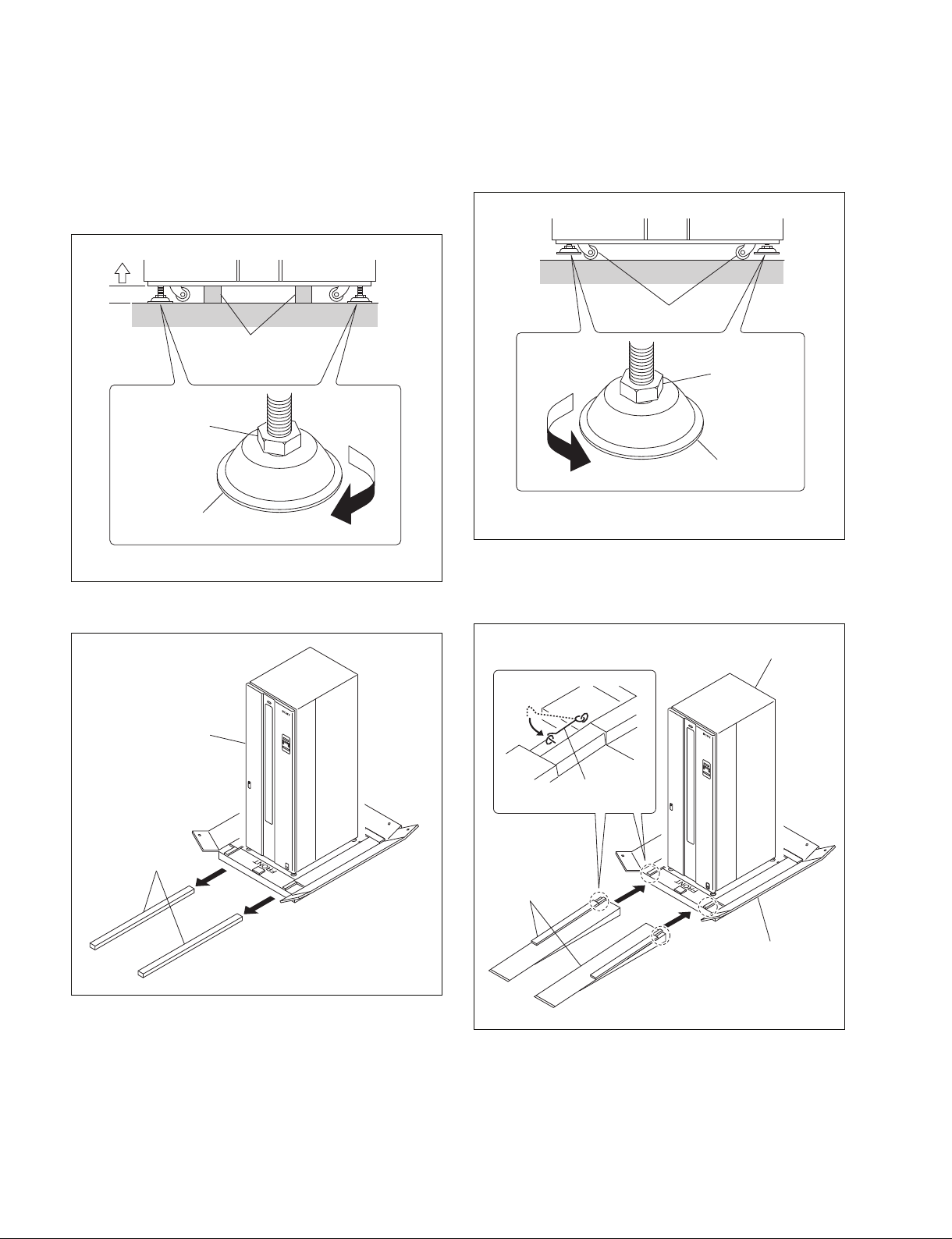
1. Rotate the leveling feet on the bottom of the machine
in the direction of the arrow until they reach the
ground. Rotate the hex-head bolts with a spanner
wrench to raise the machine until the spacers can be
removed.
3. Raise the leveling feet until the casters reach the
ground. Continue rotating the leveling feet until they
reach the upper-most positions.
Leveling foot
Hex-head bolt
Spacer
Casters
Leveling foot
Hex-head bolt
Spacers
PDJ-A640
Bottom tray
Slopes
Fixing hook
PDJ-A640
2. Remove the two spacers.
4. Attach the slope to the bottom tray and engage the
fixing hook with the loop on the slope.
5. Bring down the PDJ-A640 from the bottom tray using
the slopes.
Table of contents


